Smart electronic muzzle reference light source

a reference light source and electronic technology, applied in the direction of fluid pressure measurement, ammunition loading, instruments, etc., can solve the problems of inability to exploit the effect of tritium acquisition, handling and disposal, and inability to incorporate an on/off switch into any design,

Inactive Publication Date: 2000-06-06
ARMY GOVERNMENT OF THE US SEC THE
View PDF3 Cites 5 Cited by
  • Summary
  • Abstract
  • Description
  • Claims
  • Application Information

AI Technical Summary

Problems solved by technology

The costs associated with the acquisition, handling and disposal of tritium are high.
Typically, a MRS is used only for minutes out of each year and traditional battery operated devices cannot exploit this fact.
Incorporating an ON / OFF switch into any design is unacceptable because of potential damage to any external wiring and the dangers to the crew associated with operating an externally switched MRS in combat.
Maintaining electrical contact with the battery terminals is a major problem given the environmental extremes under which the MRS must operate.
In addition, the costs and environmental hazards associated with disposing of tens of thousands of batteries every year are very high.
Furthermore, since the Light Emitting Diode (LED) is always active in traditional designs, the entire Muzzle Reference System unit, including the housing must be replaced every five (5) years due to the limited life of the LED.

Method used


Image

  • Smart electronic muzzle reference light source
  • Smart electronic muzzle reference light source
  • Smart electronic muzzle reference light source

Examples


Embodiment Construction

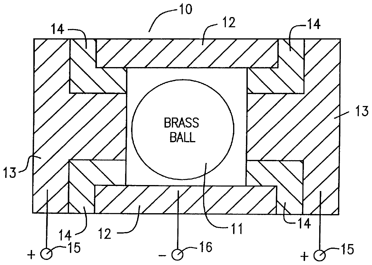
Shown in FIG. 1 is the cross-section of the sensing element 10. The sensing element 10, which is in essence a switch, consists of a small, electrically conducting sphere 11 that is able to move within the confines of a small, hollow conducting cylinder 12 with end cap closure 13. The sphere 11 clearance is 0.017 and .phi. 0.093. The wall of the cylinder 12 is conductive as are the end caps 13, each of which is separated from the cylinder wall 12 by an insulator 14. The end caps 13 are electrically connected and form one pole 15 of the switch 10. The cylinder wall 12 forms the other pole 16.

When the sphere 11 is in contact with either of the end plates 13 and the cylinder wall 12, the switch 10 is mechanically closed. However, the contact resistance determines if the switch 10 is electrically closed. As the sphere 11 rolls, electrical contract with the wall 12 is intermittent, producing a time varying electrical signal. The sensor 10 was selected because of its extremely small size, ...


PUM


Abstract

An electronic light source which replaces the hazardous tritium light source used in the existing Muzzle Reference System (MRS) found on the M1 Series of tanks. The MRS is mounted near the muzzle end of the gun (opposite the breech) and is used by tank gunness to measure gun deflection for calibration of the tank's fire control computer to optimize accuracy. The electronic light source is an LED which is activated by the pulses from a microcontroller based on the input received from a small, low power, omnidirectional motion sensor which detects the movement of the tank mounted on the tank. In the current implementation, the motion sensor comprises a conductive rolling sphere in a cylindrical chamber having a conductive wall with one electrical pole and end plates electrically insulated from the conductive wall and having the other electrical pole such that movement of the element caused by movement of the cylinder will generate intermittent electrical contact between one end plate and the cylinder wall. The signals produced are fed to the microcontroller which through the operation of its oscillator energizes the LED. The oscillator frequency is selected to eliminate EMI detection. The activation of the LED is prepared in such a manner to extend battery lite by minimizing power drain, a thermometer is employed for temperature control of the LED and other electronic circuit elements.

Description

1. Field of InventionThis invention applies to the field of systems and for apparatus which are used as monitoring devices attached to the muzzle end of large caliber guns (opposite breech) for use in measuring gun deflection for calibration purposes. Moreover the invention includes the field of low power, omnidirectional, motion sensors capable of detecting low magnitude vibrations. Lastly, the field of the invention encompasses use of electronic light sources which are used to replace radioluminescent sources such as tritium.2. Background of the InventionThe specific problem solved by this invention is one of replacing the hazardous tritium light source used in the existing Muzzle Reference System (MRS) found on the M1 series of tanks. However, the invention also applies to any type of artillary where muzzle deflection must be measured. The Muzzle Reference System (MRS) is mounted near the end of the gun (opposite the breech) and is used by tank gunners to measure muzzle deflectio...

Claims


Application Information

Patent Timeline
Patent Type & Authority Patents(United States)
IPC IPC(8): F41A1/00
CPCF41A1/00
Inventor JOHNSON, MARK A.COTE, PAUL J.
Owner ARMY GOVERNMENT OF THE US SEC THE
Why Eureka
Try Eureka