Portable telephone system and control method therefor

a telephone system and portability technology, applied in the field of portability telephone systems, can solve the problems of not being able to use call-back functions, not being able to cancel camp-on functions, and remaining unaware of the cancellation of camp-on functions

Inactive Publication Date: 2000-06-27
NEC CORP
View PDF14 Cites 41 Cited by
  • Summary
  • Abstract
  • Description
  • Claims
  • Application Information

AI Technical Summary

Problems solved by technology

However, this system has the drawback that the call is returned only once to the registrant who is the caller under the camp-on function, and if the registrant is away from the portable telephone or cannot answer the telephone when the call is returned, the camp-on function will be canceled after a standard period of time unless the phone is taken off the hook.
Thus, if the registrant has not heard the return call, he may remain unaware that the camp-on function has been canceled.
This system has the drawback that the call-back function cannot be used when the mobile terminal on the call destination side is out of range.
This is because when the call destination terminal is out of range, it is not possible to achieve a connection, so that the telephone number of the caller terminal cannot be stored in the call destination terminal.
Therefore, even if the caller urgently wishes to contact the called party, the return call will be delayed if the called party decides to postpone the return call.

Method used


Image

  • Portable telephone system and control method therefor
  • Portable telephone system and control method therefor
  • Portable telephone system and control method therefor

Examples


first embodiment

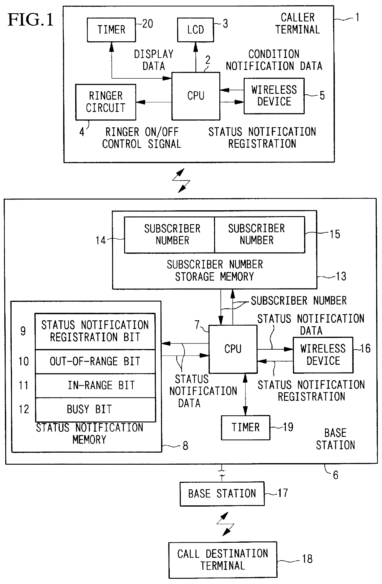
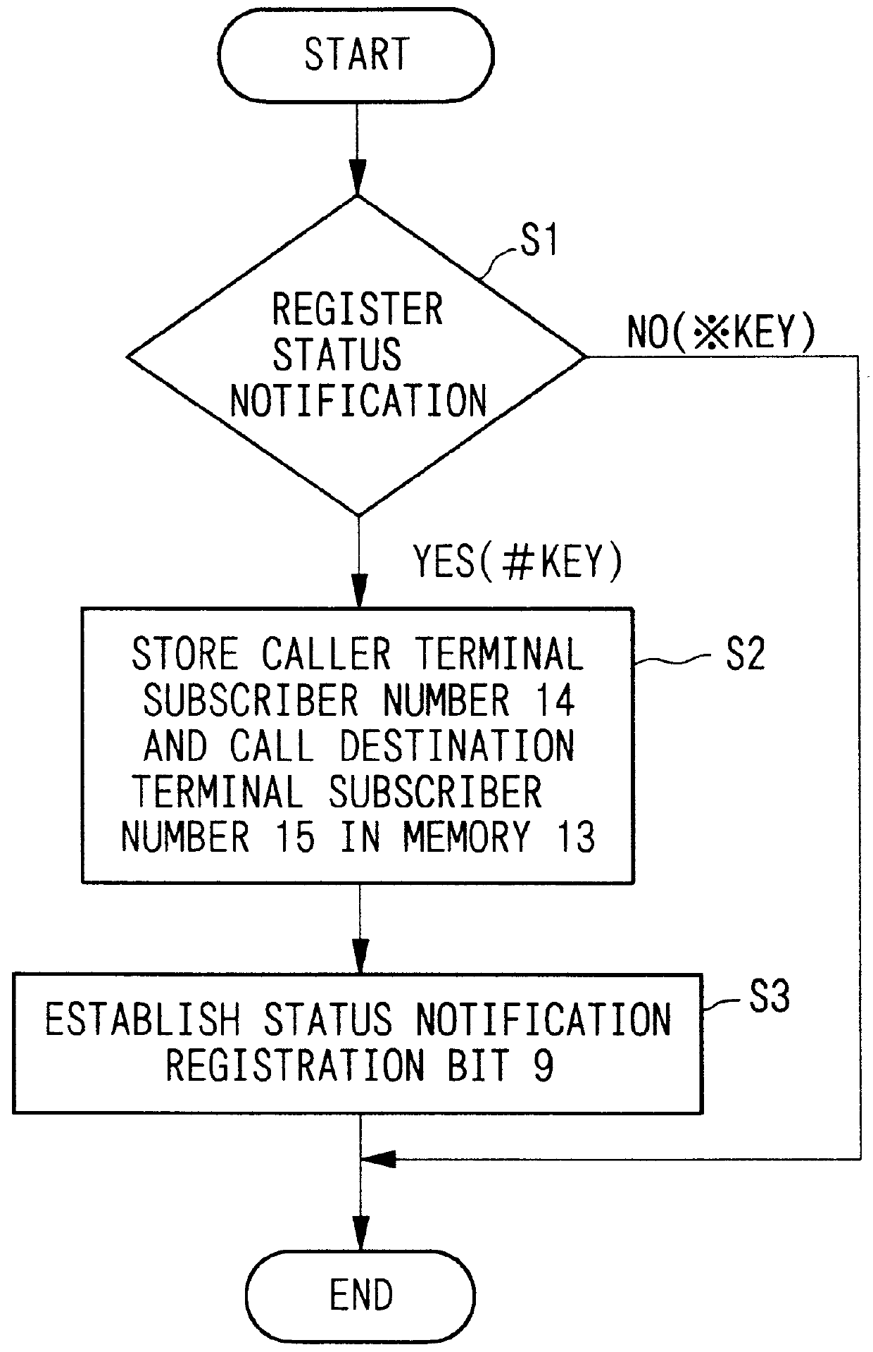
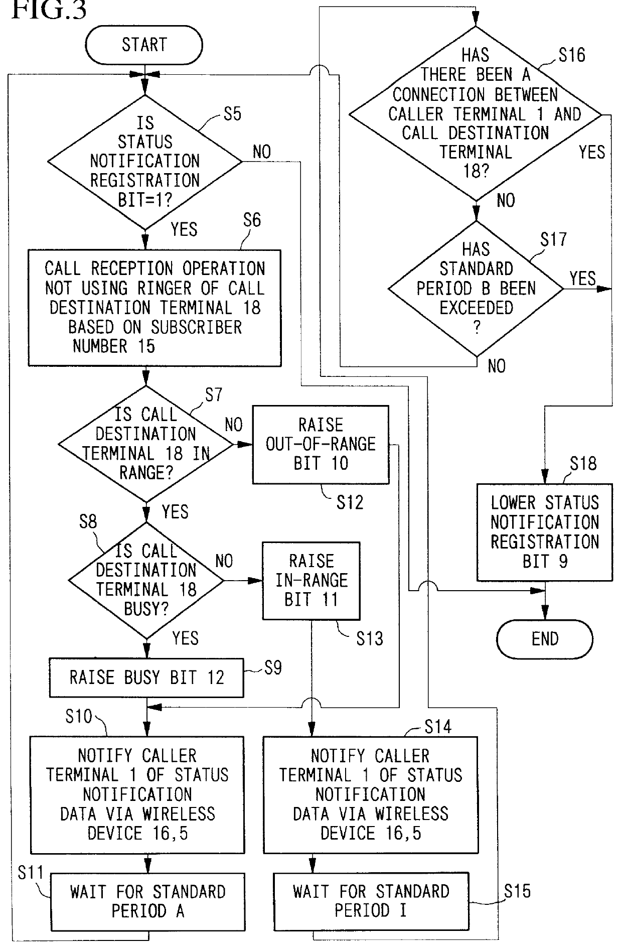
An embodiment of the present invention shall be explained in detail with reference to the drawings. FIG. 1 is a drawing showing the structure of an embodiment of the present invention. In FIG. 1, the mobile communication system is composed of a caller terminal 1, a call destination terminal 18, a base station 6 and a base station 17. FIG. 2 is a flow chart for the function whereby the base stations 6 and 17 notify the caller terminal 1 of the status of the call destination terminal 18. FIG. 3 is a flow chart for the function whereby the base stations 6 and 17 detect the status of the call destination terminal 18 and notify the caller terminal 1 of the status.

Referring to FIG. 1, the base station 6 of the present embodiment is composed of a CPU 7, a call destination terminal status notification memory 8, a subscriber number storage memory 13, and a wireless device 16. The call destination terminal status notification memory 8 has a call destination terminal status notification regist...

second embodiment

Next, the operations of the present invention shall be explained by means of a second embodiment with reference to FIG. 6, in the same manner as the First Embodiment was explained with reference to FIG. 5. The present embodiment demonstrates a case wherein a status notification registration of the call destination terminal 18 is performed at the caller terminal 1, but the caller is away from the caller terminal 1 when the caller terminal 1 is notified by the base station 6 that the call destination terminal 18 is within communication range and the ringer of the caller terminal 1 is activated.

(1) The caller terminal 1 waits for a standard period of time according to the timer 20, then, stops activating the ringer by means of the ringer circuit 4 after the standard period of time has passed, then continuously displays on the LCD 3 that the call destination terminal is within range.

(2) The base station 6 performs a call destination status detection every standard period of time until a...

third embodiment

In the present embodiment, the call destination terminal is not switched on, in which case the call destination terminal is outside of communication range. Additionally, there is a single base station.

When a call is made from the portable telephone of the caller terminal 1 to the portable telephone of the call destination terminal 18, and the call destination terminal 18 is not within range of electromagnetic communication or the call destination terminal 18 is turned off, then the subscriber number of the caller terminal 1 and the subscriber number of the call destination terminal are stored in the base station.

When the call destination terminal 18 has entered communication range or the call destination terminal 18 has been turned on, the base station detects that the call destination terminal 18 identified by the data stored in the base station has entered communication due to the registration of the position of the call destination terminal 18.

Next, the base station 6 sends data ...


PUM


Abstract

The invention has the object of notifying a caller terminal when it is not possible to connect with a call destination terminal in a portable telephone system, in order to avoid further calls to the call destination terminal while it is still not possible to achieve a connection with the call destination terminal. With the invention, it is possible to confirm whether or not the call destination terminal is capable of connecting, continually monitor the status of the call destination terminal, and to be informed immediately when it becomes possible to achieve a connection due to the activation of a ringer. Additionally, even if the ringer which gives notification that connection is possible is activated while the caller is away from the caller terminal, the caller is able to be notified that connection is possible later by looking at a display on the caller terminal.

Description

1. Field of the InventionThe present invention relates to portable telephone systems and methods for controlling such systems, particularly to telephone systems provided with the capability of periodically notifying a caller terminal of the status of the call destination terminal when the call destination terminal is busy or outside communication range until connection is made possible, and to methods for controlling such portable telephone systems. This application is based on Patent Application No. Hei 8-288290 filed in Japan, the content of which is incorporated herein by reference.2. Background ArtRecently, portable telephone systems have been introduced as one type of telephone network. These portable telephone systems often employ a cellular format wherein a base station is provided every few kilometers and there are multiple service areas.According to a conventional technique described in Japanese Patent Application, First Publication No. Hei 4-337951, when a call destination...

Claims


Application Information

Patent Timeline
Patent Type & Authority Patents(United States)
IPC IPC(8): H04M1/725H04M1/72H04Q7/22H04Q7/38H04M1/724H04M1/72505H04M1/72516H04W4/16
CPCH04M1/72505H04W4/16H04M1/72519H04M1/72516H04M3/424H04M1/724
Inventor ISHIDA, TAKESHI
Owner NEC CORP
Why Eureka
Try Eureka