

Apparatus and method for changing a video image to a drawing-style image
a technology of video and image, applied in the direction of image enhancement, color signal processing circuit, instruments, etc., can solve the problems of requiring much labor and time for making linear drawing and painting by means of human handwork
- Summary
- Abstract
- Description
- Claims
- Application Information
AI Technical Summary
Problems solved by technology
Method used
Image

Examples
first embodiment
(1) First Embodiment
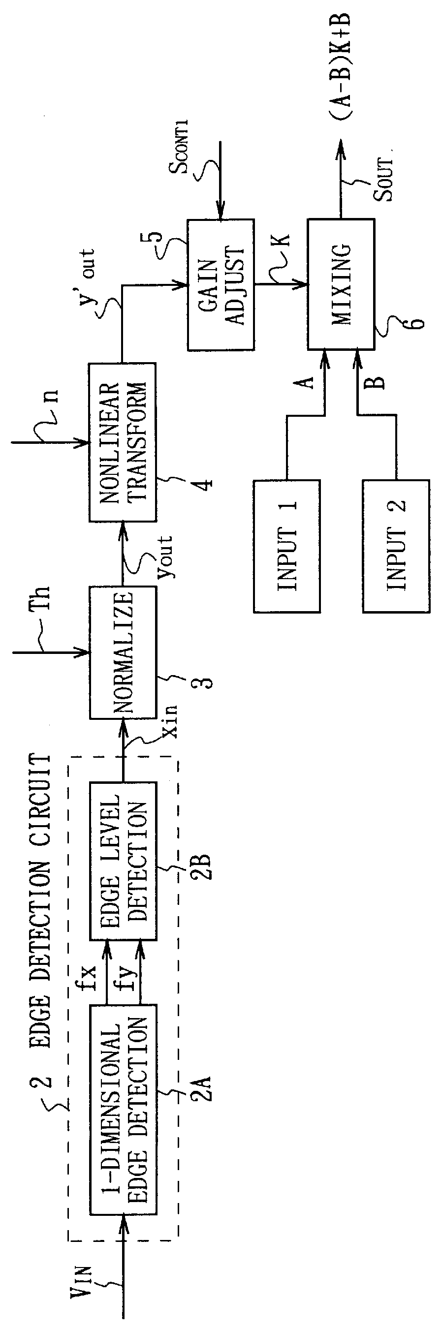
FIG. 1 shows an example of the construction of image transforming device suited for the use in case of transforming an original image to the drawing. Each part of the image transforming device 1 is constructed as follows:
An edge detection circuit 2 is a circuit which receives an input image signal V.sub.IN of an input image f and detects its edge. Here, the edge detection circuit 2 utilizes the characteristic that the edge which human can recognize is the localized region where light and gray level change rapidly. More specifically, it will be detected by using the brightness differential value.
The edge detection circuit 2 differentiates the inputted image in the horizontal direction (x direction) and in the vertical direction (y direction) at a one-dimensional edge detection circuit 2A. In the figure the differential in the x direction is shown by fx and the differential in the y direction is shown by fy.
Furthermore, in the digital image processing assisted by t...
second embodiment
(2) Second Embodiment
In FIG. 5, in which the corresponding parts of FIG. 1 are given the same reference numerals, the construction of a image transform device which can be suitably applied to the case when transforming an original image to the painting style will be shown.
In an image transform device 11, the parts different from FIG. 1 will be described. In the case of this image transform device 11, the edge element A extracted from the input image f and the color element B of the input image f are mixed in the fixed proportion K at a mixing circuit 6 and will be outputted.
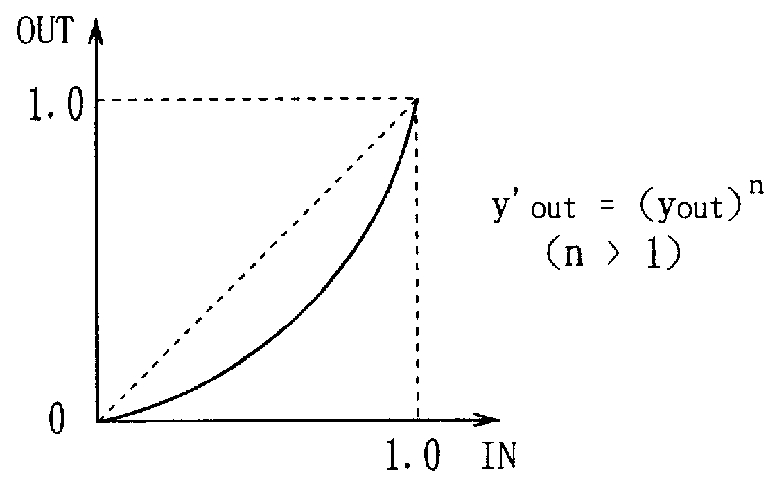
Firstly, a nonlinear transform circuit 12 placed at the latter stage of a normalization circuit 3 will be described. The direction of transform characteristic curve of nonlinear transform to be used in this picture transform is different from that of the drawing transform and an upward convex curve as shown in FIG. 6A will be used. This transform is the characteristic transform which shows the edge darker than th...
third embodiment
(3) Third Embodiment
In FIG. 9, in which corresponding parts of FIGS. 1 and 5 are designated the same reference numerals, an example of the construction of the image transform device which can be suitably used in the case of transforming an original image to a relief style will be shown.
Then, of each part of the image transform device 21, parts different from FIG. 5 will be described below. In the case of this image transform device 21, the circuit part for extracting the edge element of the input image f, i.e., an edge detection circuit 22, is characterized and the direction of light striking against the subject and the concave and convex relation of the surface of the subject can be freely changed.
A one dimensional edge detection circuit 2A and an edge level detection circuit 2B are provided in the input stage and in the output stage of the edge detection circuit 22 similar to the form of the embodiment described above. However, the edge detection circuit 22 of this embodiment is c...
PUM
 Abstract
Description
Claims
Application Information