Vacuum loading system

a vacuum loading and vacuum technology, applied in the direction of conveyor control devices, conveyor parts, bulk conveyors, etc., can solve the problems of frequent maintenance and replacement, cloth filter wear, and clogging of cloth filters rather quickly

Inactive Publication Date: 2000-07-18
MAGUIRE STEPHEN B
View PDF57 Cites 51 Cited by
  • Summary
  • Abstract
  • Description
  • Claims
  • Application Information

AI Technical Summary

Problems solved by technology

The cloth filters typically become clogged rather quickly, requiring frequent maintenance and replacement.
Cloth filters also wear quickly from granular plastics material impact and abrasion.
These blow back devices add cost and complexity to the system.
The blast plate is preferably steel; aluminum, from which the casting is preferably made, usually wears too quickly.
This positioning of the blast shield within the deceleration chamber allows the air / material mix to spread into a larger flow area, thus losing speed.

Method used


Image

  • Vacuum loading system
  • Vacuum loading system
  • Vacuum loading system

Examples


Embodiment Construction

Referring to the drawings in general and to FIG. 30 in particular, a vacuum loading system in accordance with the preferred embodiment of the invention is designated generally 10 and is used to provide granular material to two or more devices requiring such granular material. In the embodiment illustrated in FIG. 30, the devices requiring such granular material are a pair of gravimetric blenders each designated 12. The gravimetric blenders are preferably mounted on molding machines designated generally 14, which are preferably of the injection molding type. Each gravimetric blender 12 includes a hopper 16, which is preferably divided internally into compartments being supplied with granular material.

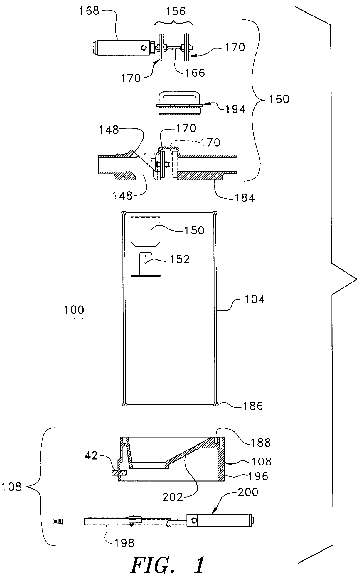
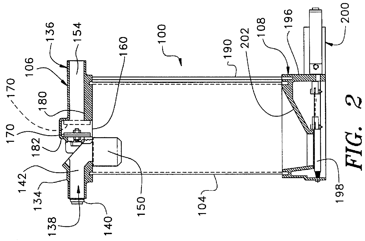
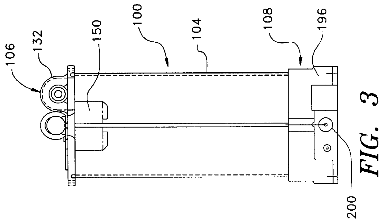
Vacuum loading system 10 includes at least one receptacle designated generally 100. A plurality of such receptacles 100 are illustrated in FIG. 30. Each receptacle 100 is preferably mounted on top of hopper 16 and is in communication with one of the internal compartments of hopper 16.

The...


PUM

PropertyMeasurementUnit
angleaaaaaaaaaa
angleaaaaaaaaaa
diameteraaaaaaaaaa

Abstract

Apparatus and methods for providing granular material to a loading hopper preparatory to processing, provide an at least partially transparent receptacle for receiving material prior to processing machinery supplied by the hopper with the receptacle having a top, a valve for selectably connecting the receptacle to vacuum or to ambient air, vacuum drawn in the receptacle, a conduit connecting the receptacle to a supply of granular material, a valve selectably permitting material flow from the receptacle into the hopper and control temporally adjustably closing the first valve and opening the second valve responsively to visually detected presence of a suitable amount of material in the receptacle.

Description

BACKGROUND OF THE INVENTION--FIELD OF THE INVENTIONThis invention relates to methods and apparatus for feeding granular and powdery type materials to receptacles for storage of such materials prior to processing the materials upon removal from the receptacles. Specifically, this invention relates to methods and apparatus for feeding granular plastic resin materials and additives for granular plastic resin materials to receptacles for storage temporarily in the receptacles prior to removal of the resin materials for processing by plastic molding and extrusion machinery.BACKGROUND OF THE INVENTION--DESCRIPTION OF THE PRIOR ARTIn the plastics industry automatic material conveying has been used for many years with vacuum being a common means for such conveying.Blowers are sometimes used to provide positive pressure conveying. In blower-driven systems, cyclone separators separate air from conveyed plastic resinous material prior to delivery to the material to a final delivery point.Howev...

Claims


Application Information

Patent Timeline
Patent Type & Authority Patents(United States)
IPC IPC(8): B65G43/08B65G53/66B65G53/34
CPCB65G53/66B65G53/24B29B7/60
Inventor MAGUIRE, STEPHEN B.
Owner MAGUIRE STEPHEN B
Why Eureka
Try Eureka