In-line flow rate control device

a flow rate control and flow rate technology, applied in process and machine control, instruments, transportation items, etc., can solve the problems of difficult and costly manufacture, lack of ease of adjustment, and complex construction of controllers

Inactive Publication Date: 2000-08-01
PESCADERO BEACH HLDG
View PDF9 Cites 75 Cited by
  • Summary
  • Abstract
  • Description
  • Claims
  • Application Information

AI Technical Summary

Problems solved by technology

A common drawback of many of the prior art flow controllers is that the controllers are often complex in construction, are difficult and costl

Method used


Image

  • In-line flow rate control device
  • In-line flow rate control device
  • In-line flow rate control device

Examples


Embodiment Construction

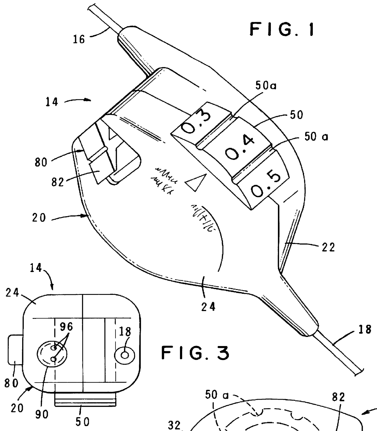
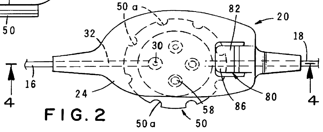
Referring to the drawings and particularly to FIGS. 1 through 5, one form of the adjustable rate control device of the present invention is there illustrated and generally designated by the numeral 14. As illustrated in FIGS. 1 and 2, the device is adapted to be interposed between a fluid supply 16 line which is interconnected with a source of fluid under pressure (not shown) and a fluid delivery line 18 which can be interconnected with a remote site to which the fluid is to be delivered at a controlled rate.

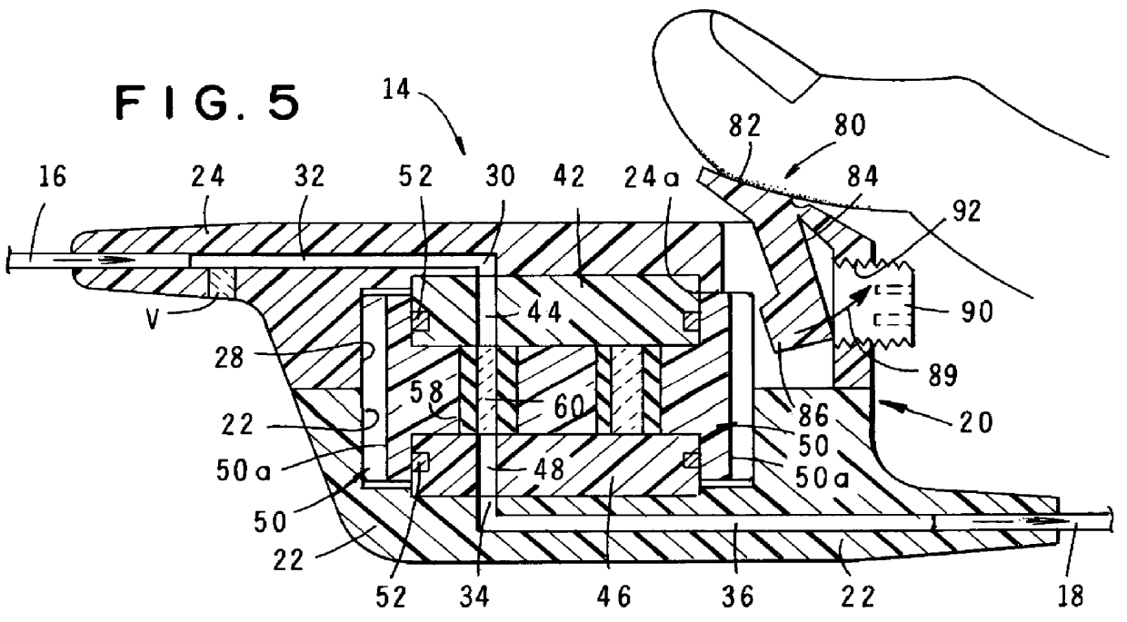
The device of the present form of the invention comprises a hollow housing 20 which is made up of a base portion 22 and an interconnected cover portion 24. As best seen in FIGS. 4 and 6, base portion 22 is provided with an internal cavity 22a and cover 24 is provided with an internal cavity 24a so that when the components are connected in the manner shown in FIGS. 1 through 4, an internal chamber 28 is formed. Chamber 28 has a fluid inlet 30 which is in communication with an inl...


PUM


Abstract

A readily adjustable flow rate control device having a movable flow control member which includes a plurality of spaced-apart flow restrictors which are adapted to be selectively positioned intermediate a fluid flow path extending between a fluid supply line and a fluid delivery line. The flow restrictors can take the form of porous rate control frits which can be selectively moved into index with the fluid flow path or microbores formed in a rotatable member which can be rotated to selectively move the microbores into index with the fluid flow path.

Description

1. Field of the InventionThe present invention relates generally to fluid flow rate control devices for controlling the rate of fluid flow from a fluid source to a remote location. More particularly, the invention concerns a novel, readily adjustable flow rate control device having a movable flow control member which includes a plurality of spaced-apart flow restrictors which are adapted to be selectively positioned intermediate a fluid supply line and a fluid delivery line.2. Discussion of the Prior ArtA very large number of in-line fluid flow controllers for use in controlling the rate of fluid flow from a fluid supply line into a fluid delivery line have been suggested in the past. These types of devices are used in countless applications where it is necessary to control the rate at which fluid flows from a fluid source to a remote delivery point via fluid supply and delivery lines.A frequently used application of prior art fluid flow devices is to control the rate of infusion of...

Claims


Application Information

Patent Timeline
IPC IPC(8): A61M5/168F16K3/00F16K3/32
CPCA61M5/16881F16K3/32Y10T137/6895
Inventor KRIESEL, MARSHALL S.
Owner PESCADERO BEACH HLDG
Why Eureka
Try Eureka