Atmospheric effects simulation

a technology of atmospheric effects and simulation, applied in the field of atmospheric effects simulation, can solve the problems of inability to provide a realistic simulation of snow, inability to provide a realistic simulation and inability to achieve realistic simulations in a sufficiently large volume of worldspa

Inactive Publication Date: 2000-08-08
REDIFON SIMULATION LTD
View PDF4 Cites 6 Cited by
  • Summary
  • Abstract
  • Description
  • Claims
  • Application Information

AI Technical Summary

Problems solved by technology

Attempts to provide realistic simulations of snow have to date not been successful.
Whereas in non-real time systems any required level of detail can be produced providing sufficient computing power and time is available, this is not the case in real time systems where the computational resources available to generate a single image are necessarily limited.
Although such a system was successful in providing a realistic image in these limited circumstances, it could not provide a realistic simulation in a sufficiently large volume of worldspace to en...

Method used


Image

  • Atmospheric effects simulation
  • Atmospheric effects simulation
  • Atmospheric effects simulation

Examples


Embodiment Construction

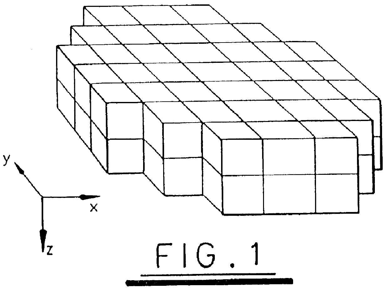
FIG. 1 is a three-dimensional representation of a model made up from seventy four cubes arranged in two layers. The model is used to simulate snow in a simulator which generates an image of a worldspace through which an aircraft flies. Assuming a worldspace co-ordinate system x, y, z as represented in FIG. 1, the model will move through worldspace in the directions of each of the three axes but will not rotate relative to these axes. Accordingly the edges of each cube will always be parallel to one of the three axes. Each cube portion of the model structure is occupied by an identical object representing the movement of snow within a volume corresponding to the volume of the cube. Typically each cube will have one hundred foot sides such that the model structure is two hundred feet high.

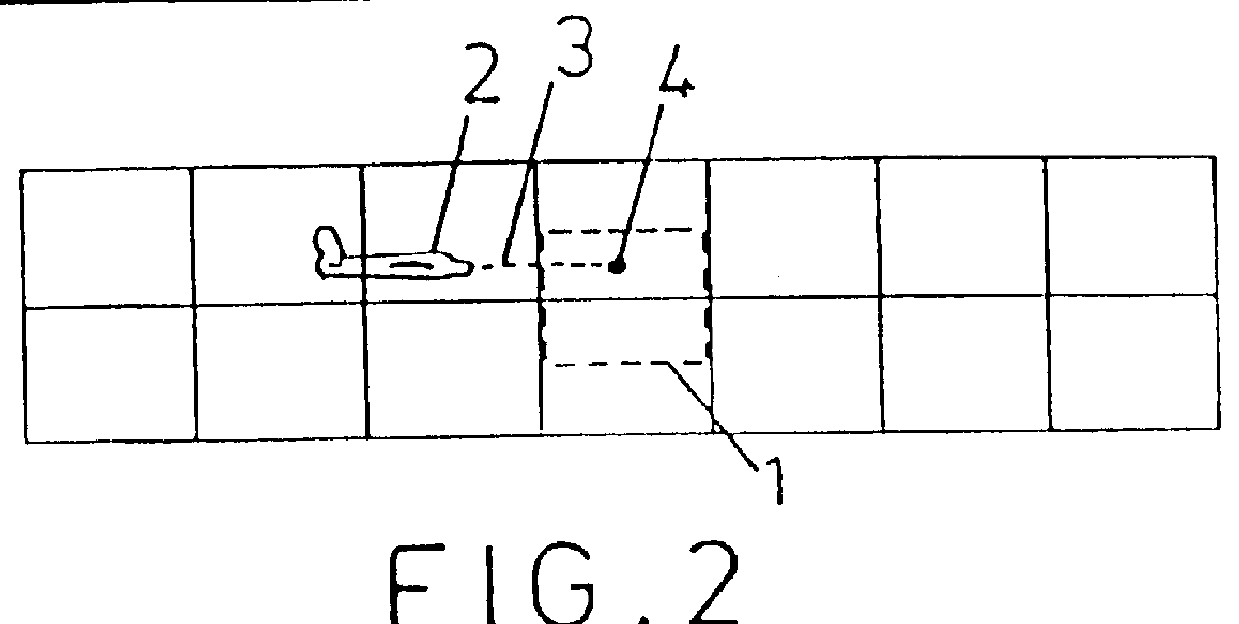
FIG. 2 is a side view of the model structure of FIG. 1, and FIG. 3 is a plan view of the model structure of FIG. 1. In FIGS. 2 and 3, a notional space 1 which is located centrally with respect to the...


PUM


Abstract

PCT No. PCT/GB96/01484 Sec. 371 Date Mar. 13, 1998 Sec. 102(e) Date Mar. 13, 1998 PCT Filed Jun. 24, 1996 PCT Pub. No. WO97/03417 PCT Pub. Date Jan. 30, 1997The motion of particles such as snow is simulated in a computer generated image which represents the appearance from a predetermined viewing point of a three-dimensional worldspace through which the particles move. A three-dimensional model is defined which is made up from a regular array of abutting cubes of predetermined dimension. An object is defined which dimensions correspond to the dimensions of each cube, the object having characteristics such that it represents the motion of particles through the volume which it occupies. The three-dimensional model made up of the array of cubes is notionally positioned in worldspace such that the viewing point is located within a region of the model selected such that the field of view of particles from the viewing point is always within the model. As the viewing point travels through worldspace, it is translated in steps with the magnitude of each step corresponding to the length of any one side of the cubes. The model is moved in worldspace so as to maintain the viewing point within the selected region of the model. The image which is generated includes the model in which the object representing the moving particles occupies each of the cubes. The visibility of the cubes is faded out with distance from the viewing point so as to conceal the boundaries of the model. The model is positioned relative to the viewing point such that a notional point on a line drawn through the viewing point in a predetermined direction relative to the viewing point motion is always within a predetermined central region of the model. The distance between the notional point and the viewing point is a function of the speed of movement of the viewing point.

Description

1. Field of the InventionThe present invention relates to an apparatus and method for simulating the appearance of atmospheric effects such as snow in a computer generated image.2. Related ArtSimulators are well known which are capable of generating an image on a screen used by for example a trainee pilot. The image is generated from a database of digital information representing for example terrain and buildings as they appear from a viewpoint which may move relative to the terrain. The digital data thus represents a model of a worldspace and the images are representative of the appearance of that worldspace from a particular position. Generally the model will be based on a series of planar polygonal objects of known geometry, position, orientation and surface attributes. Examples of such systems are described for example in U.S. Pat. Nos. 5,363,475 and 5,412,796. The first of these two U.S. patents describes the basic operation of an image generator in terms of dealing with the pr...

Claims


Application Information

Patent Timeline
IPC IPC(8): G06T15/10G09B9/00
CPCG06T15/10
Inventor HICKS, TIMOTHY J.OLIVE, GRAHAM J.BERRIDGE, PAUL H.
Owner REDIFON SIMULATION LTD
Why Eureka
Try Eureka