Apparatus and method of determining conditions of bank notes

a technology of condition determination and apparatus, applied in the field of apparatus and method of determining conditions of bank notes, can solve the problems of limiting the speed at which notes can be processed, limiting their usefulness, and limitations of prior art devices, and achieve the effect of economic use and manufactur

Inactive Publication Date: 2000-08-08
DIEBOLD NIXDORF
View PDF176 Cites 242 Cited by
  • Summary
  • Abstract
  • Description
  • Claims
  • Application Information

AI Technical Summary

Benefits of technology

It is a further object of the present invention to provide an apparatus that indicates the identity of a note, that is economical to use and

Problems solved by technology

All such prior art devices have limitations.
This requires the device to include a mechanism to align the notes and often limits the speed at which the notes can be processed.
This limits their usefulness as notes are often not presented in a uniform orientation.
This presents drawbacks as other note types cannot be processed.
Often it is difficult or impossible to adapt such devices to handle currencies of countries which have different physical properties.
Furthermore, it may be difficult to adapt such devices to a new printing series of notes within the same country.
Many prior art devices are also amenable to compromise by counterfeit notes.
However, currency notes in circulation change properties through use fairly quickly.
Notes in circulation may change their properties through handling and wear.
Notes may become dirty or marked with ink or other substances.
Notes may also lose their color due to having been mistakenly washed with clothing or exposed to water or sunlight.
Prio

Method used


Image

  • Apparatus and method of determining conditions of bank notes
  • Apparatus and method of determining conditions of bank notes
  • Apparatus and method of determining conditions of bank notes

Examples


Embodiment Construction

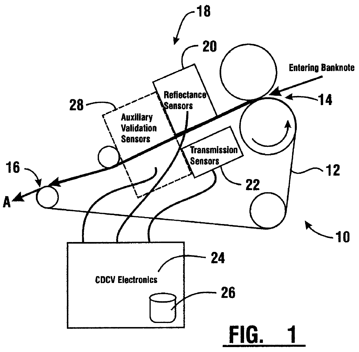
Referring now to the drawings and particularly to FIG. 1, there is shown therein one preferred embodiment of an apparatus of the present invention generally indicated 10. The apparatus includes a note transport 12. Transport 12 is preferably a belt-type transport that moves sheets such as currency notes one at a time from an entry end 14 to an exit end 16. Sheets such as notes move on the transport 12 in a note direction indicated by Arrow A.

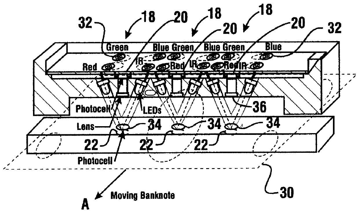
The apparatus of the present invention also includes a plurality of spot sensing assemblies 18. The preferred form of the invention shown includes three spot sensing assemblies which are spaced from one another in a direction transverse of the note direction of note movement (see FIG. 3).

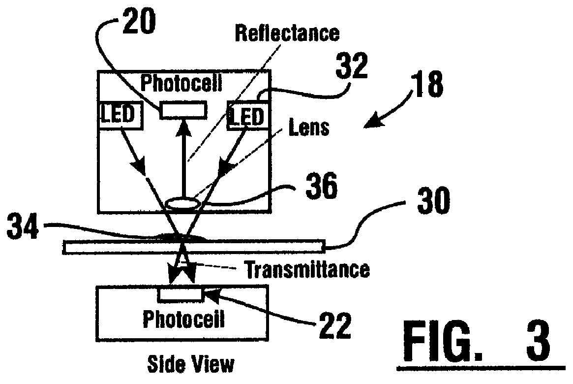
Each of the spot sensing assemblies includes a reflectance detector, schematically indicated 20. Each spot sensing assembly 18 also includes a transmission detector schematically indicated 22. As indicated in FIG. 1 the reflectance detector 20 is in operative co...


PUM


Abstract

An apparatus and method for providing an indication of a type and/or a condition of a note passing through the apparatus includes a note transport (12) which moves the note past transversely spaced spot sensing assemblies (18). Each spot sensing assembly includes four emitters (32). Each of the emitters produces radiation at different wavelengths. The spot sensing assemblies include a reflectance detector (20) and a transmission detector (22) which are disposed on opposed sides of the passing note. The emitters direct radiation onto test spots (34) on the passing note. Radiation reflected from and transmitted through the test spots is detected by the respective reflector and transmission detectors. A control circuit (24) produces sensed values that correspond to the detected radiation. A data store in operative connection with the control circuit comprises memories (138) that include stored data representative of transition and reflectance values for know note types. The control circuit calculates a level of correlation between the stored values and the sensed values. By comparing the correlated values to threshold values, the control circuit is operative to determine the type of note and other conditions such as if a note is worn, soiled, or a doubles note.

Description

This invention relates to devices for identifying the type and validity of documents. Specifically this invention relates to devices and methods for identifying the denomination and authenticity of currency notes, and for determining conditions of currency notes.Numerous devices have been previously developed for identifying documents and determining their authenticity. Likewise, devices have been previously developed for determining the denomination and authenticity of bank and currency notes. Such devices commonly test different properties of a presented note and based on the properties sensed, give an indication of the denomination and / or authenticity of the presented note. All such prior art devices have limitations.Many prior art devices require precise alignment of the note during sensing of its properties. This requires the device to include a mechanism to align the notes and often limits the speed at which the notes can be processed. In addition, some devices require that pr...

Claims


Application Information

Patent Timeline
IPC IPC(8): G07D7/12G07D7/00G07D7/20
CPCG07D7/12G07D7/20
Inventor LASKOWSKI, EDWARD L.MA, SONGTAO
Owner DIEBOLD NIXDORF
Why Eureka
Try Eureka