

Cable joint structure
Inactive Publication Date: 2000-08-15
CHUO SPRING
View PDF7 Cites 15 Cited by
- Summary
- Abstract
- Description
- Claims
- Application Information
AI Technical Summary
Benefits of technology
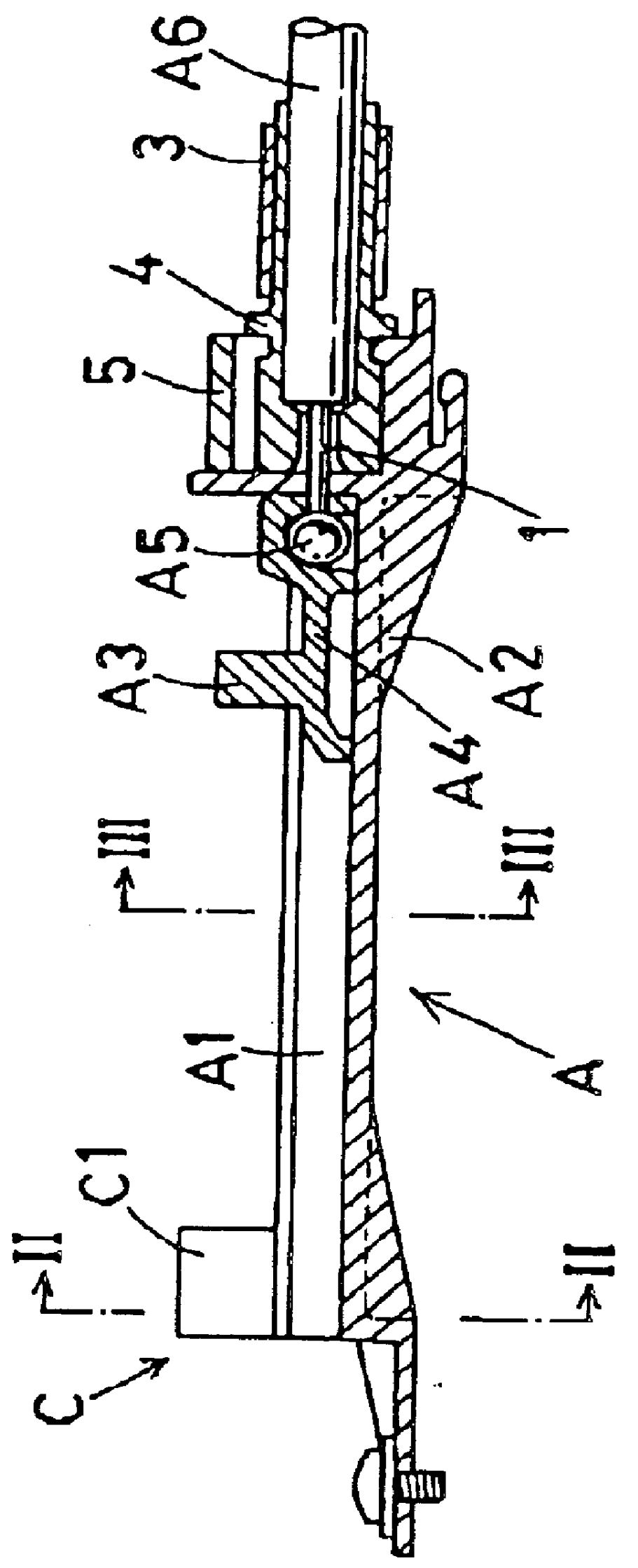
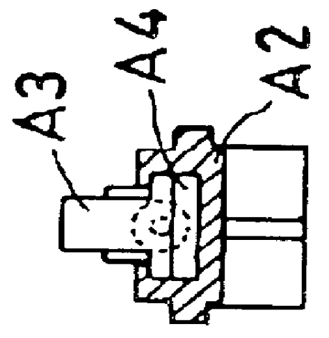
(i) With the two-step operation necessary to connect the first cable 1 to the second cable 2 as opposed the prior art in which the three-step operation has been demanded, it is possible to readily complete the wire connecting procedures even for those who are unaccustomed to the cable joint operation.(ii) Due to the first end portion (A4) and the second end portions (B4) each retained by the first rail members (A1) and the second rail member (B1), it is possible to connect and disconnect the cables 1, 2 with a single hand operation because there is no necessity to hold the first end portion (B4) and the second end portions (A4) during the operation.(iii) Because of no torsional force induced between the casing (A2, B2) and the end portion (A4, B4), there is no possibility to appear the torsional friction therebetween. This makes it possible to move the cables 1, 2 smoothly with the least burden.Modification FormIt is to be observed that the present cable joint structure can be used to connect and disconnect two or more paired cables instead of only one paired cables 1, 2.
Problems solved by technology
This, however, requires the three-step procedure which results in a complicated and time-consuming operation.
For this reason, it is difficult to handle the cable joint structure particularly for those who are not accustomed to operating the cable joint structure.
Method used
View moreImage
Smart ImageViewing Examples


Examples
modification form
It is to be observed that the present cable joint structure can be used to connect and disconnect two or more paired cables instead of only one paired cables 1, 2.
Login to View More PUM
 Abstract
In a cable joint structure, a first casing has a first rail member. A first end portion has a lug portion directed opposite to the first rail, and connected to one end of a first cable so that the first end portion moves along the first rail member. A second casing has a second rail member. A second end portion has a recess portion into which the lug portion interfits from a direction opposite to the second rail member, and connected to one end of a second cable so that the second end portion moves along the second rail member. A lock member is provided to unite the first casing to the second casing with the first rail member located to face the second rail member.
Description
1. Field of the InventionThe invention relates to a cable joint structure used to detachably connect two cables.2. Description of Prior ArtIn a cable joint structure of FIG. 14, there has been provided a rectangular casing (J1) in which a first casing cap (J4) is disposed to attach a first outer casing (J3) of a first cable (J2) to one side of the casing (J1). To one end of the first cable (J2), a first end portion (J6) is connected in the manner to slide within the casing (J1). The first end portion (J6) has a key-shaped hole (J5). A second casing cap (J9) is provided to attach a second outer casing (J8) of a second cable (J7) to the other side of the casing (J1). To one end of the second cable (J7), a spherical portion (J10) is connected as a second end portion which interfits into the key-shaped hole (J5). A lid cap (J11) is provided to shield an open ended area of the casing (J1).Upon connecting the first cable (J2) to the second cable (J7), the spherical portion (J10) of the se...
Claims
Login to View More Application Information
Patent Timeline
 IPC IPC(8): F16C1/22F16C1/10F16C1/12B65H69/00F16C1/14H02G7/02H02G15/02
CPCF16C1/101F16C1/22Y10T74/20462Y10T403/587Y10T403/5706F16B2200/71
InventorTSUGE, YOSHIKATSU
OwnerCHUO SPRING