Riser joint and apparatus for its assembly

a technology of risers and joints, applied in mechanical equipment, hose connections, drilling pipes, etc., can solve the problems of complex joint construction, vessel rise and fall on water level, connection failure, etc., to facilitate rapid make-up and/or release of each joint, facilitate rapid and safe disassembly, and facilitate rapid make-up and/or release

Inactive Publication Date: 2000-08-22
COOPER CAMERON CORP
View PDF23 Cites 56 Cited by
  • Summary
  • Abstract
  • Description
  • Claims
  • Application Information

AI Technical Summary

Benefits of technology

is to provide a riser connector and deployment system which can be used with drilling, workover, completion, intervention, or production operations for conventional vessel riser supporting techniques or self-supporting freestanding buoyant riser applications. Another objective of the invention is to provide equipment which will facilitate the rapid make-up and / or release of each joint. Yet another objective is to provide a high-strength joint that will provide the performance capability of oilfield premium joints. Another objective is to be able to provide a joint which can be made-up quickly and disassembled quickly and safely. Simplicity of the design and strength and performance are also objectives of the joint in question. Those and other objectives will be evident from a review of the preferred embodiment of the invention described below.

Problems solved by technology

When joints of pipe are subjected to a combination of tension loads and oscillatory bending loads, such loadings can cause stress reversals which, in turn, can cause the connection to fail.
Such loadings are a particular issue when pipe joints are connected as part of a riser pipe extending vertically between a wellhead, x-mas tree, and an offshore location and a tensioning device or supporting device aboard a drilling vessel from which operations could be conducted.
the vessel rises and falls on the water level, but also to bending loads due to the water currents.
Some of the disadvantages of this technique are that each joint has to be specially designed and that the nut has to be rotated with appropriate power tools for each joint to hold the desired tension.
The joint construction is complicated, making each joint expensive to manufacture such that the entire riser string which contains numerous joints winds up being a substantial investment for the well operator.
Additionally, there are hazards involved in operation of the nut while one component of the joint is subjected to stresses.

Method used


Image

  • Riser joint and apparatus for its assembly
  • Riser joint and apparatus for its assembly
  • Riser joint and apparatus for its assembly

Examples


Embodiment Construction

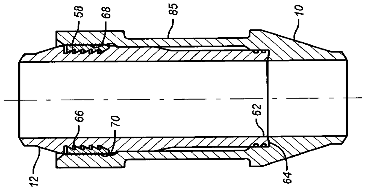
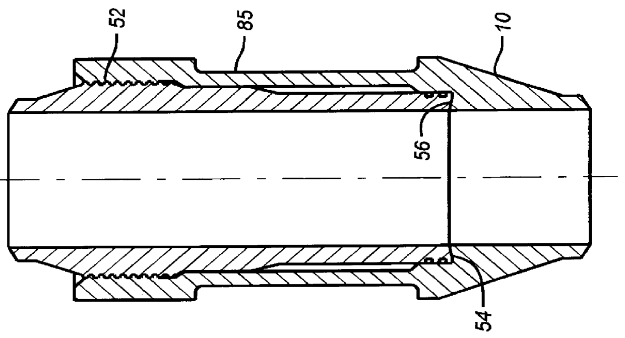
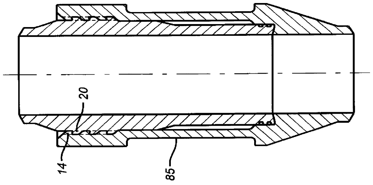
The joint of the present invention is preferably made of a box end 10 and a pin end 12. In a breech lock style for the present invention shown in FIGS. 7 and 9, the box 10" has circumferentially spaced projections 14, separated by circumferential spaces 16 such that in the design depicted in FIG. 7, there are three separate projections 14 above each other to form rows of projections 14, each separated by an axial space 18. As shown in FIG. 7, the projections 14 are radial projections. The pin 12" has projections 20 which are circumferentially distributed on its outer surface 22. The pin 12" has a lower end 24 which is insertable into opening 26 at the top of the box 10 (see FIG. 8). The projections 20 on the pin 12" have circumferential spaces 28 and axial spaces 30 such that, as shown in FIG. 9, there are shown a stack of three projections 20 which form discrete rows of projections 20.

To make up the joint illustrated in FIGS. 7-10, the box 10" is preferably stretched with a spider ...


PUM


Abstract

A joint design particularly useful in subsea risers is disclosed. The joint is preferably of a pin and box design where one of the components is held in a stressed condition as the joint is made up and locked together. A portion of the applied stress is then removed, leaving a preload in the assembled joint. A hydraulically operated tool is used to apply the stress while at the same time supporting the riser string. The joint can seal with resilient seals or metal-to-metal contact, or both. The locking device can be of a variety of types including but not limited to breech lock, threads, or lock rings. The pin and box may be made of different materials that have different yield strengths and moduli of elasticity.

Description

FIELD OF THE INVENTIONThe field of this invention relates to equipment and techniques for assembling joints in subsea risers, particularly where strains are to be built-in to the assembled joint.BACKGROUND OF THE INVENTIONWhen joints of pipe are subjected to a combination of tension loads and oscillatory bending loads, such loadings can cause stress reversals which, in turn, can cause the connection to fail. Such loadings are a particular issue when pipe joints are connected as part of a riser pipe extending vertically between a wellhead, x-mas tree, and an offshore location and a tensioning device or supporting device aboard a drilling vessel from which operations could be conducted. The riser pipe, which can extend to a length of several thousand feet, is not only subjected to tension loads asthe vessel rises and falls on the water level, but also to bending loads due to the water currents. To deal with such situations, a pipe connector has been proposed in U.S. Pat. No. 4,012,059...

Claims


Application Information

Patent Timeline
Patent Type & Authority Patents(United States)
IPC IPC(8): E21B17/02E21B17/08E21B17/046E21B17/042
CPCE21B17/046E21B17/085E21B17/042E21B17/0465
Inventor HERMAN, RICHARD J.FLOYD, MICHEAL D.
Owner COOPER CAMERON CORP
Why Eureka
Try Eureka