Multi-optical-path photoelectric switch

a photoelectric switch and optical path technology, applied in the direction of optical elements, pulse techniques, instruments, etc., can solve the problems of insufficient mechanical durability, unsatisfactory strength of the intermediate portion of the multi-optical path photoelectric switch for maintaining the connection among units, and insufficient rigidity to achieve satisfactory mechanical durability. , to achieve the effect of satisfying rigidity and mechanical strength

Inactive Publication Date: 2000-08-29
KEYENCE
View PDF3 Cites 7 Cited by
  • Summary
  • Abstract
  • Description
  • Claims
  • Application Information

AI Technical Summary

Benefits of technology

In view of the foregoing, an object of the present invention is to provide a multi-optical-path photoelectric switch having satisfactory rigidity and mechanical strength for maintaining the connection among the units.
According to the present invention, the overall body of the first case structured such that at least the surface adjacent to the optical paths of the light emitting devices or the light receiving devices is made of the light transmissive resin material is received and held by the fixing frame. Moreover, a portion of the fixing frame is accommodated by the second case. Thus, the units are formed. The units are mechanically and electrically connected to one another. Therefore, the fixing frame formed into a double wall structure because the fixing frame holds the first case is disposed to penetrate second cases of adjacent units. Therefore, the rigidity of the multi-optical-path photoelectric switch constituted by connecting the units to one another can be increased. Moreover, durability against external oscillations and impact can be improved. Even if the number of units which must be connected is increased and thus the overall length is elongated, the mechanical strength for maintaining the connection among the units can be increased.

Problems solved by technology

Therefore, there arises problems in that realized rigidity is insufficient to obtain satisfactory mechanical durability against external oscillations and impact.
If the number of units which must be connected to one another increases and thus the overall length of the multi-optical-path photoelectric switch is elongated, there arises a problem in that the strength of the intermediate portion of the multi-optical-path photoelectric switch for maintaining the connection among units becomes unsatisfactory.

Method used


Image

  • Multi-optical-path photoelectric switch
  • Multi-optical-path photoelectric switch
  • Multi-optical-path photoelectric switch

Examples


Embodiment Construction

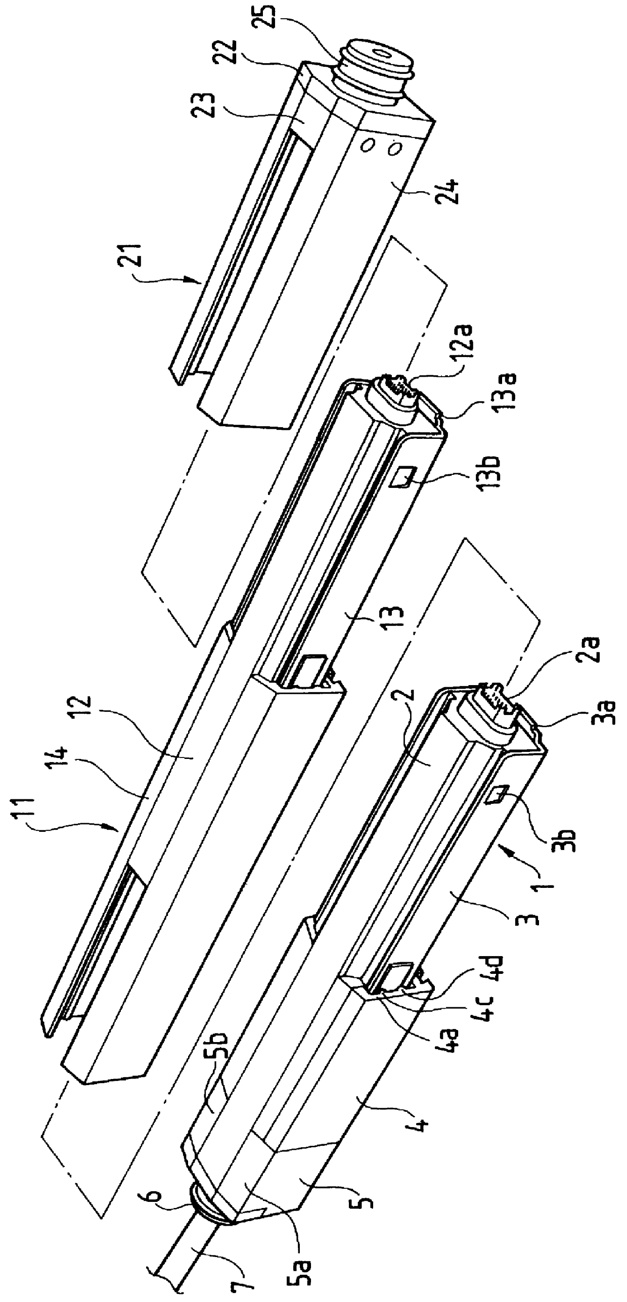
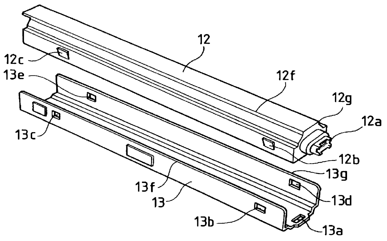
An embodiment of the present invention will now be described with reference to FIGS. 1 to 9. Note that the structures of a light emitting portion and a light receiving portion according to the present invention are the same except for the corresponding devices, that is, the light emitting devices or the light receiving devices. Therefore, only either of the structures will now be described. FIG. 2 is an exploded perspective view showing an inner case and a fixing frame which are elements of an extension unit. Referring to FIG. 2, an inner case 12 is made of a sealing material composed of a light transmissive synthetic resin and arranged to seal a required number of light emitting devices or light receiving devices, the inner case 12 serving as a first case. A male connector 12a is disposed at an end of the inner case 12. A female connector is disposed at another end of the inner case 12.

Projections 12b and 12c are formed on the side surface of the inner case 12. Projections 12d and ...


PUM


Abstract

A light emitting portion of a multi-optical-path photoelectric switch comprising: a predetermined number of light emitting devices for emitting lights; a first case having a male connector disposed at one end, a female connector diposed at the other end, a surface between both ends made of a light transmissive resin, the surface through which the lights from the light emitting devices pass; a fixing frame holding the first case, and having the substantialy same length as the first case; and a second case accommodating a portion of the fixing frame while a residual portion of the fixing frrame is projected therefrom, wherein the light emitting units are mechanically and electrically connected to one another by inserting the portion of the fixing frame thus projected of either of adjacent light emitting units into the second case of the other adjacent light emitting unit. A light receiving portion of the multi-optical-path photoelectric switch comprises the similar structure.

Description

The present invention relates to a multi-optical-path photoelectric switch having a light emitting portion incorporating a plurality of light emitting devices and a light receiving portion having the same number of light receiving devices as that of the light emitting devices.As a photoelectric switch for detecting a predetermined area, a multi-optical-path photoelectric switch is known which is structured as shown in FIG. 10 and which incorporates optical paths, the number of which can be varied. FIG. 10 is a perspective view showing a multi-optical-path photoelectric switch having six optical paths or channels, the multi-optical-path photoelectric switch having a light emitting portion 51 and a light receiving portion 52 disposed opposite to each other. The light emitting portion 51 has six light emitting devices (not shown). The light receiving portion 52 has six light receiving devices 53a to 53f therein. The light emitting devices and the corresponding light receiving devices 5...

Claims


Application Information

Patent Timeline
Patent Type & Authority Patents(United States)
IPC IPC(8): H03K17/94H01H35/00
CPCH03K17/941
Inventor IWASAKI, KOUMEIOKA, MICHIAKI
Owner KEYENCE
Why Eureka
Try Eureka