Treadmill for wheelchair

a technology for treadmills and wheelchairs, applied in the direction of gymnastic exercise, frictional force resistors, sport apparatus, etc., can solve the problems of inertial force loss, increased floor space, and difficulty in achieving the effect of reducing the number of steps

Inactive Publication Date: 2000-09-05
SUNCREA CORP
View PDF5 Cites 35 Cited by
  • Summary
  • Abstract
  • Description
  • Claims
  • Application Information

AI Technical Summary

Problems solved by technology

The exercising platform as firstly mentioned above may allow for the adjustment of the resistance or load to be applied against the rotary motion of the rollers on which the wheelchair wheels are supported, but it has several problems yet to be solved.
For example, when the load to be applied against the rotary motion of the rollers is provided by friction, the inertial force may be lost.
For the trainer including the separate device for providing the load to be applied against the rotary motion of the rollers, as secondly mentioned above, the device must be provided as an external device, which requires extra floor space and which also complicates the mechanical construction.
Specifically, the problems associated with the exercising platform that remain yet to be solved include making the wheelchair wheels unstable on the rollers during the actual training exercise, making it difficult or impossible to adjust the angle between the roller shaft on the platform and the wheel shaft on the wheelchair, and making it difficult to guide the wheelchair wheels onto the platform.
More specifically, if it is difficult or impossible to adjust the angle of inclination of the roller shaft with regard to the wheel shaft when the latter is inclined during the training exercise, and thus the wheelchair becomes unstable, and its side wheels might slip out of the rollers.
Furthermore, the exercising platform has another problem yet to be solved in that there is no means for controlling the means for adjusting the resistance or load to be applied against the rotary motion of the rollers.
The trainer which permits the user of the wheelchair to conduct the training exercise by operating either of the side wheels has some problems yet to be solved, with particular regard to the stability of the wheelchair wheels on the treadmill rollers and the ease of controlling the various adjusting means.

Method used


Image

  • Treadmill for wheelchair
  • Treadmill for wheelchair
  • Treadmill for wheelchair

Examples


first embodiment

(First Embodiment)

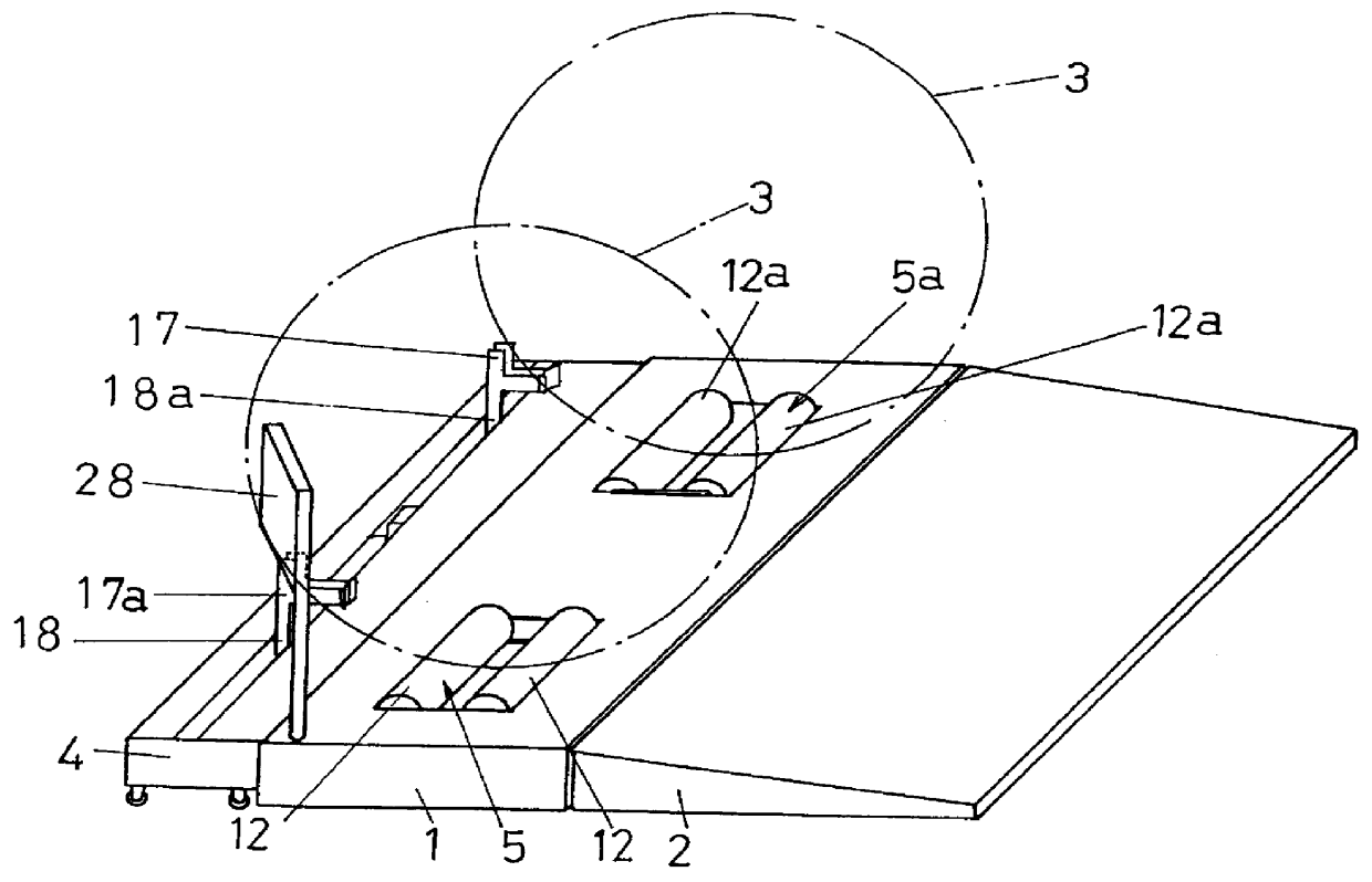
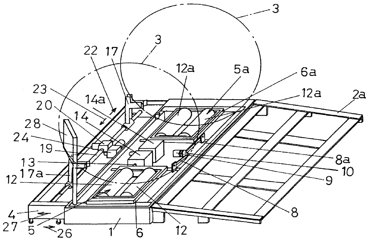
Referring to FIGS. 1, 2, 3(a), 3(b), 4(a), and 4(b), a first embodiment of the present invention is described. The treadmill for wheelchairs according to the first embodiment of the present invention includes a casing 1 forming a main body of the treadmill, an auxiliary casing 2 operatively connected to one side (rear side) of the casing 1 for advancing the wheelchair onto the treadmill, and a guide casing 4 operatively connected to the other side (front side) of the casing 1 for guiding side wheels 3, 3 on the wheelchair and being capable of movement closer to or away from the casing 1 (FIGS. 1 and 2). The auxiliary casing 2 is supported on an internal crossbar structure 2a as shown in FIG. 2. The casing 1 contains two sets of roller support frames 6, 6a, for example, which are arranged on the left and right sides of the casing 1 and in parallel with each other (FIG. 2).

The roller support frames 6, 6a have an identical construction, and the following description i...

second embodiment

(Second Embodiment)

Referring next to FIGS. 5, 6, 7(a), 7(b), 8(a), 8(b), 9(a), 9(b), 10 and 11, a second embodiment of the present invention is described. The body of the treadmill formed by a rectangular platform 31 includes two sets of parallel rollers 34, 34 mounted for rotatably supporting the side wheels 33, 33 of a wheelchair 32 thereon (FIGS. 5, 6). The diameter and length of the rollers 34, 34, and the distance between the rollers may be determined depending upon the particular dimensional requirements for the wheelchair. The two sets of rollers 34, 34 have an identical construction, and the following description is only provided for one set of rollers 34, 34, which may also apply to the other set of rollers.

The rollers 34, 34 are rotatably supported on shafts 35, 35 which are mounted across a roller support frame 36, 36. One side (center side of the platform 31) of the roller support frame 36 is fixed at its bottom to a support rod 38 by way of a hinge 37, the support rod 3...

third embodiment

(Third Embodiment)

According to a third embodiment shown in FIG. 12, the stopper 81 and the display 79 may be mounted either on the front or rear side of the platform 31. Specifically, the treadmill according to this embodiment allows the person on the wheelchair to move up either on the front or rear side of the casing 31 and conduct the training exercise. Differently from the preceding embodiment shown in FIGS. 5 through 11, the roller support frame 36 is preferably mounted nearer to the center area of the platform 31.

In all of the embodiments, including the third embodiment, the roller support frame 36 may be mounted, removed and / or reoriented. In the embodiment shown in FIG. 5, the roller support frame 36 is mounted such that the flywheel 53 is placed on the front side of the platform 31. In the embodiments shown FIGS. 6 and 12, the roller support frame 36 is mounted such that the flywheel 53 is placed on the rear side of the platform 31. Any of the embodiments allows for mountin...


PUM


Abstract

A treadmill includes a braking device incorporated in the body of the treadmill and operated for applying a resistance or load against the rotary motion of treadmill rollers on which a wheelchair's side wheels are supported. The angle of inclination of the treadmill rollers may be adjusted according to any variation in the angle of inclination for the wheelchair wheels supported by the treadmill rollers. To this end, the user of the wheelchair can adjust the angle of inclination for the treadmill rollers. A guide member for supporting the front wheel of the wheelchair may also be included, and the guide member can be adjusted to accommodate practically all types and sizes of the wheelchair. A central control panel is provided at a particular single point on the treadmill for enabling the user of the wheelchair to control the braking device, adjust the angle of inclination, and moving the guide member.

Description

1. Field of the InventionThe present invention relates to a treadmill for wheelchairs that is designed to help a person or occupant on a wheelchair learn how to operate the side wheels on the wheelchair, to permit the person on the wheelchair to practice physical muscular training and other like exercise motions, and to practice rehabilitating exercises and the like. More particularly, the present invention relates to a treadmill for wheelchairs that is designed to permit a person or occupant on a wheelchair to adjust the mechanical resistance or load to be applied against the rotary motion of the treadmill rollers on which the wheelchair's side wheels are supported, to permit him or her on the wheelchair to adjust the angle of inclination of the treadmill rollers according to any variation in the angle of inclination for the wheelchair wheels, and to permit the wheelchair to be supported on the treadmill with safety, reliability and stability during training and other exercises on ...

Claims


Application Information

Patent Timeline
Patent Type & Authority Patents(United States)
IPC IPC(8): A63B69/16A63B21/00A63B21/015A63B21/012A63B21/22A63B71/00A63B71/02
CPCA63B71/0009A63B21/015A63B21/225A63B69/16A63B2071/0018A63B2071/025
Inventor GOTO, MORIKI
Owner SUNCREA CORP
Why Eureka
Try Eureka