Method and apparatus for testing a fluid conduit system for leaks

a fluid conduit and system technology, applied in the direction of measuring devices, structural/machine measurement, instruments, etc., can solve the problems of system not yet stabilised, system may not be fully functional, and pressure may initially rise on closing the stop cock before it starts

Inactive Publication Date: 2000-09-12
BRITISH GAS PLC
View PDF6 Cites 28 Cited by
  • Summary
  • Abstract
  • Description
  • Claims
  • Application Information

AI Technical Summary

Problems solved by technology

However, with the introduction of new, relatively low volume gas meters it will no longer be appropriate to ignore the differences in the pipework volume from system to system or the differences between different low volume gas meters and thus the assumption previously made will no longer be a valid one.
Firstly, that the stop valve is faulty a

Method used


Image

  • Method and apparatus for testing a fluid conduit system for leaks
  • Method and apparatus for testing a fluid conduit system for leaks
  • Method and apparatus for testing a fluid conduit system for leaks

Examples


Embodiment Construction

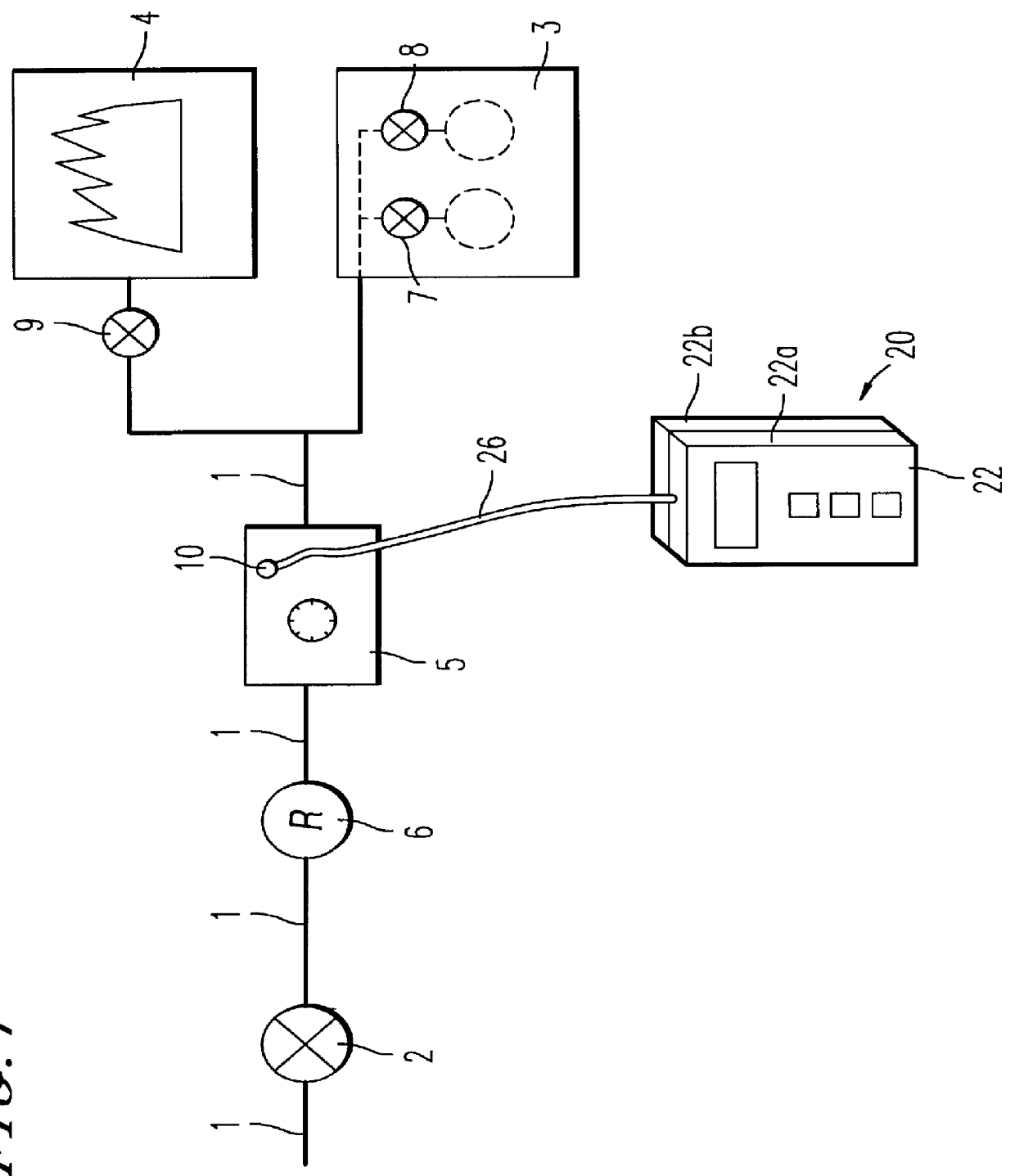
FIG. 1 schematically illustrates part of a domestic fuel gas system or installation as an example of the kind of fluid containing system on which the method and apparatus may be used in order to determine the leak rate of fluid escaping from the system.

The system comprises a gas supply pipe 1 connected to a gas main (not shown). A stop cock 2 is provided for closing off the pipe and preventing supply of gas to downstream gas-fired appliances 3 and 4 via gas meter 5.

A gas regulator or governor 6 is provided between the stop cock 2 and the gas meter 5. The gas-fired appliances 3 and 4 have associated therewith gas control valves 7, 8 and 9 via which gas can be prevented from passing through the appliances. The gas meter 5 has a normally closed tapping hole 10 via which access may be had to the interior of the system on using an appropriate tool or instrument to manipulate the tapping hole to an open position.

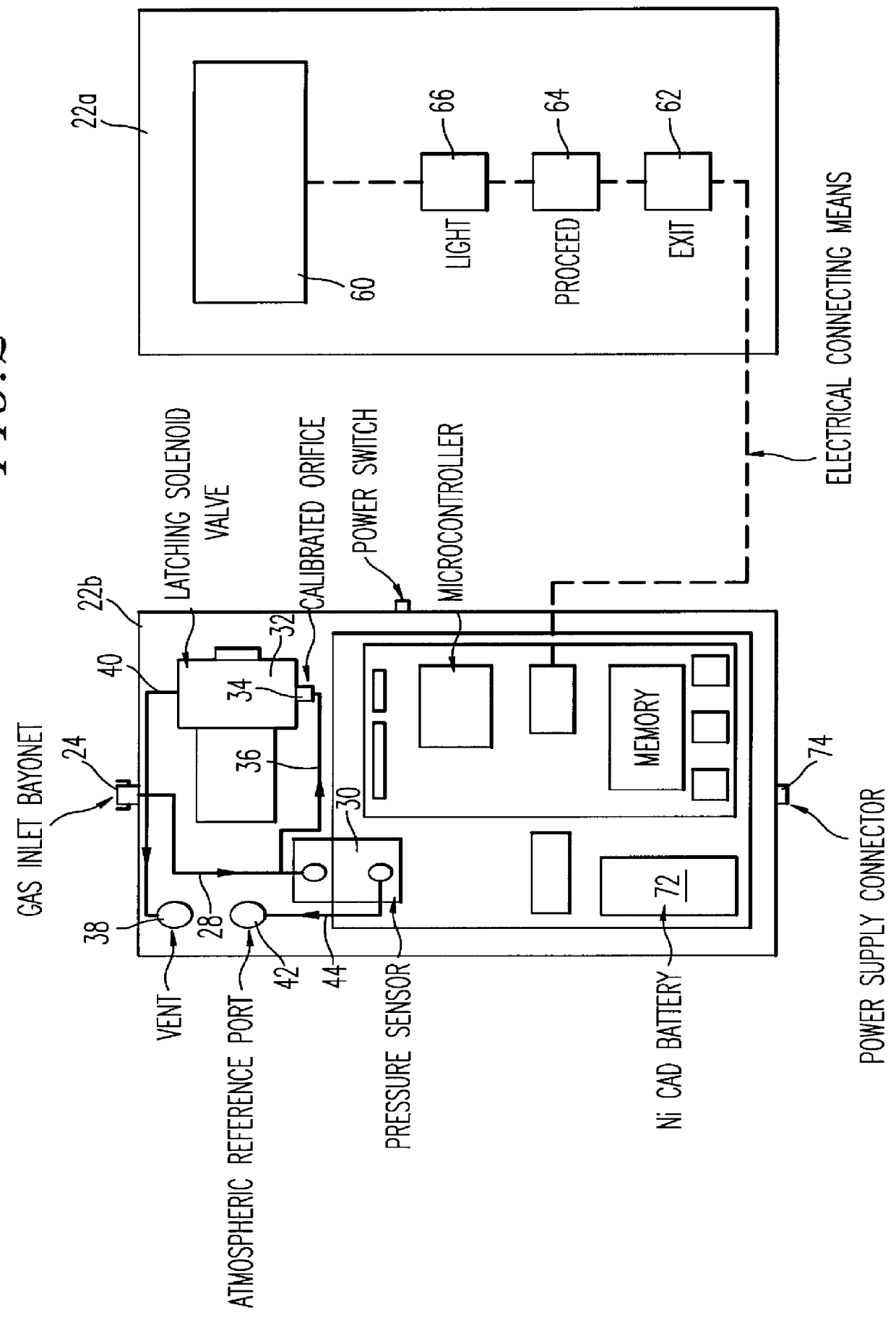
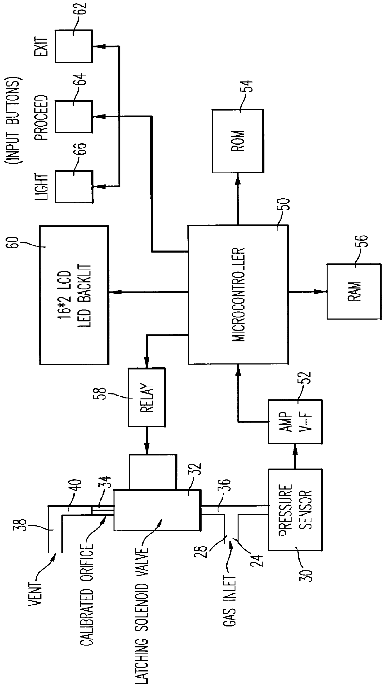
The apparatus 20 schematically illustrated in FIGS. 2 and 3 comprises upper a...


PUM


Abstract

PCT No. PCT/GB96/02571 Sec. 371 Date May 12, 1998 Sec. 102(e) Date May 12, 1998 PCT Filed Oct. 17, 1996 PCT Pub. No. WO97/14944 PCT Pub. Date Apr. 24, 1997A method and apparatus for testing a fluid conduit system for leaks. The apparatus is connected to an isolated section of a domestic fuel gas system which is suspected of leaking. The apparatus determines over recorded time periods the pressure drop in the system as a result of the actual gas leak and subsequently the pressure drop in the system as a result of an actual leak plus the leakage through an introduced artificial and calibrated orifice provided by the apparatus. The data is used in an equation for calculating the actual leakage rate from the system. This method avoids the need to repressurize the system between pressure drop measurements or having to know or assume the volume of the system being tested.

Description

1. Field of the InventionThis invention relates to a method and apparatus for testing a fluid conduit system, such as a domestic fuel gas supply system or installation, for gas leaks and, more particularly, for monitoring and determining the volumetric leakage rate of gas from such a system or installation.2. Discussion of the BackgroundThe portion of the domestic system with which the applicants are primarily concerned comprises: the pipework between the gas meter and the main stop cock or valve (normally at or fairly close to the upstream, inlet side of the gas meter); the gas meter itself; and the pipework between the outlet of the meter and the gas control valve(s) on the downstream appliance(s). One presently used method for testing such systems for leaks where there is a suspected leak involves isolating the system by closing the stop valve and the or each gas control valve, pressurising the system by opening the stop valve, closing the stop valve, and from a predetermined pre...

Claims


Application Information

Patent Timeline
IPC IPC(8): G01M3/28G01M3/26
CPCG01M3/2815G01M3/28
Inventor PRIDE, RUSSELL DESMOND
Owner BRITISH GAS PLC
Why Eureka
Try Eureka