Method and apparatus for identifying defects in a rotating machine system

a technology of rotating machines and defects, applied in the field of rotating machinery, can solve problems such as catastrophic failure, eventual failure, and defects that are not obvious, and achieve the effect of avoiding failure, avoiding failure, and avoiding failur

Inactive Publication Date: 2000-09-12
BALDOR ELECTRIC COMPANY
View PDF4 Cites 75 Cited by
  • Summary
  • Abstract
  • Description
  • Claims
  • Application Information

AI Technical Summary

Problems solved by technology

Many such rotating machinery systems are periodically subjected to considerable loading that may result in latent defects or, in severe cases, catastrophic failure.
In many cases, eventual failure is the result of continued cycling of machine elements in which defects have already occurred.
Such defects may including cracks, tears, or other deformations in the mechanical structures that will eventually fail, even under normal working stresses.
Because the failure of such machinery may lead to expensive repairs and down time, it is important to locate latent defects as early as possible to permit scheduling of necessary repairs before failures occur.
Failures due to latent defects are particularly problematic in conveyor and drive systems.
In many applications, loads are quite substantial and the machinery must remain functional virtually at all times. Failure of elements of the machinery, particularly of pulleys and rollers, results in unscheduled repairs to bring the machinery back into service.
Where the pulleys and rollers support a conveyor belt or chain, the belt may need to be removed to give access to the failed component, resulting in additional down time and expense.
Certain serious or obvious defects in rotating machine systems may be detectable by operations personnel based upon auditory or visual inspection.
However, many defects escape such detection due to their latent nature or location.
In conveyor systems in particular, certain rotating machinery may be located on booms, towers and the like, where physical inspection is very difficult.
Moreover, many latent defects are not readily discoverable even upon close visual inspection, without recourse to special equipment which is not typically available in industrial and other settings.

Method used


Image

  • Method and apparatus for identifying defects in a rotating machine system
  • Method and apparatus for identifying defects in a rotating machine system
  • Method and apparatus for identifying defects in a rotating machine system

Examples


Embodiment Construction

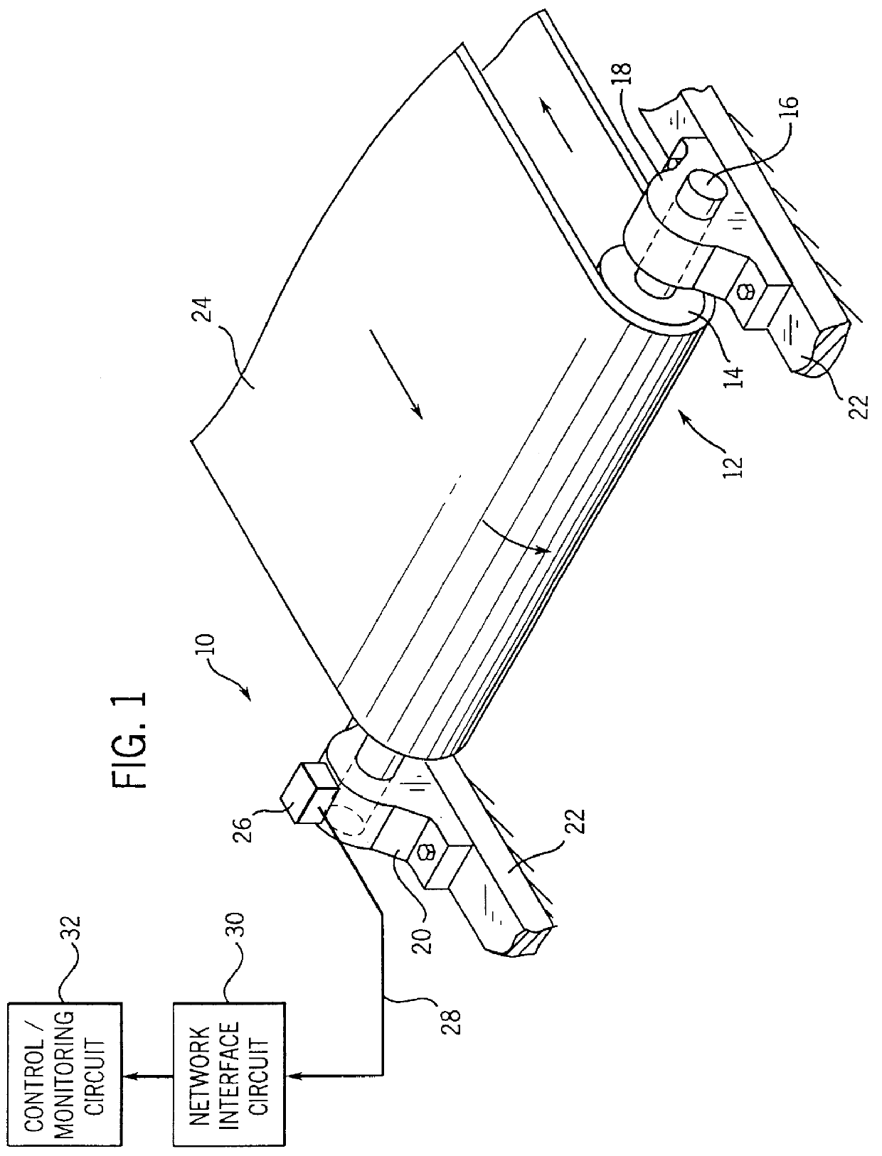
Turning now to the drawings, and referring first to FIG. 1, a defect detection and monitoring system, designated generally by the reference numeral 10, is illustrated as installed with a rotating machine system 12. In the embodiment illustrated in FIG. 1, the rotating machine system 12 includes a drum pulley 14 mounted on a rotating shaft 16. Pulley 14 and shaft 16 are supported by bearings 18 and 20 at either end of shaft 16. Bearings 18 and 20 are, in turn, rigidly supported on a machine frame, represented generally at reference numeral 22. In the particular embodiment illustrated in the figures, rotating machine system 12 enables a conveyor belt 24 to be moved about pulley 14 for material handling purposes and the like. It should be noted, however, that rotating machine system 12 may be of various configurations, including both live and dead shaft pulley systems, idler rollers, conveyors or chains and so forth.

System 10 further includes an accelerometer unit 26 secured to one of ...


PUM


Abstract

A system for detecting defects in a rotating machine system includes a sensor such as an accelerometer coupled to the machine system for detecting vibrations of a rotating element. Output of the accelerometer is transmitted, preferably via a network data link to a monitoring/control circuit. The monitoring/control circuit analyzes the vibration data to develop a normal vibration profile for the machine system during a normal operating phase. The normal vibration profile is stored in a memory circuit for later reference. During subsequent operation of the machine system, the monitoring/control circuit cyclically analyzes vibration data to develop actual vibration profiles. The actual vibration profiles are compared to the normal vibration profile and, where variations between the profiles exceed preset tolerances, the circuit provides an indication of a malfunction or defect in the machine system. The technique is particularly well suited to conveyor systems such as drum pulleys and the like in which cracks, breaks and other defects can result in unexpected failure and maintenance.

Description

1. Field of the InventionThe present invention relates to the field of rotating machinery and the monitoring of such machinery for defects, breakages and the like. More particularly, the invention relates to a system for monitoring a pulley assembly or other rotating machine element and for detecting a change in the operating condition of the assembly by reference to a vibration or load profile.2. Description of the Related ArtA variety of industrial, mining and other applications exist for rotating machinery. Such machinery includes drive systems and material handling systems, such as conveyors and the like. Many such rotating machinery systems are periodically subjected to considerable loading that may result in latent defects or, in severe cases, catastrophic failure. In many cases, eventual failure is the result of continued cycling of machine elements in which defects have already occurred. Such defects may including cracks, tears, or other deformations in the mechanical struct...

Claims


Application Information

Patent Timeline
Patent Type & Authority Patents(United States)
IPC IPC(8): G01M13/02G01H1/00
CPCG01H1/003G01M13/028G01M13/045
Inventor EL-IBIARY, YEHIA M.SARKISIAN, RICHARD L.
Owner BALDOR ELECTRIC COMPANY
Why Eureka
Try Eureka