Combination electrical/mechanical mounting connector

Inactive Publication Date: 2000-09-26
TRUETT BRETT B
View PDF20 Cites 27 Cited by
  • Summary
  • Abstract
  • Description
  • Claims
  • Application Information

AI Technical Summary

Benefits of technology

Accordingly it is an object of the present invention to provide a method and apparatus for mounting manipulating devices in p

Problems solved by technology

Apparatus of this type frequently involve movable parts and/or work pieces whic

Method used


Image

  • Combination electrical/mechanical mounting connector
  • Combination electrical/mechanical mounting connector
  • Combination electrical/mechanical mounting connector

Examples


Embodiment Construction

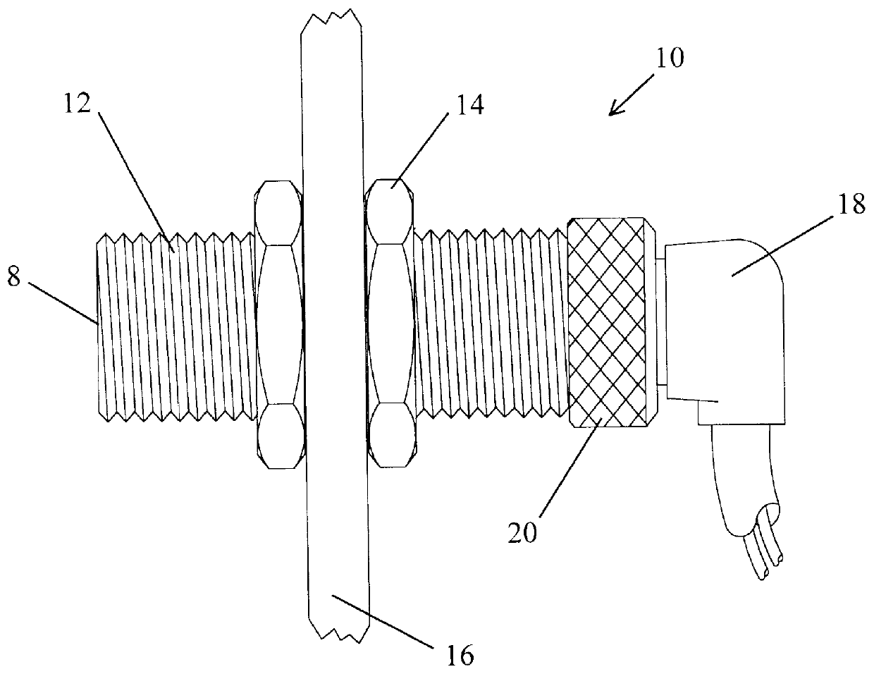
FIG. 1 shows a typical prior art device in which a tubular sensor 10 has a threaded exterior surface 12. The tubular sensor 10 is mounted on a machine by a pair of jamb nuts 14, one on either side of wall 16. A standard right angle connector cord set 18 fits on the terminal end of sensor 10 and is secured theron by a threaded nut 20. If the sensor 10 fails or is damaged, to replace it, not only must the connector 18 be removed by loosening nut 20, but the nuts 14 must be removed to replace sensor 10 with a new one. The new sensor must then be repositioned and calibrated by adjusting nuts 14 until the sensor face 8 is located at the correct position for accurate sensing.

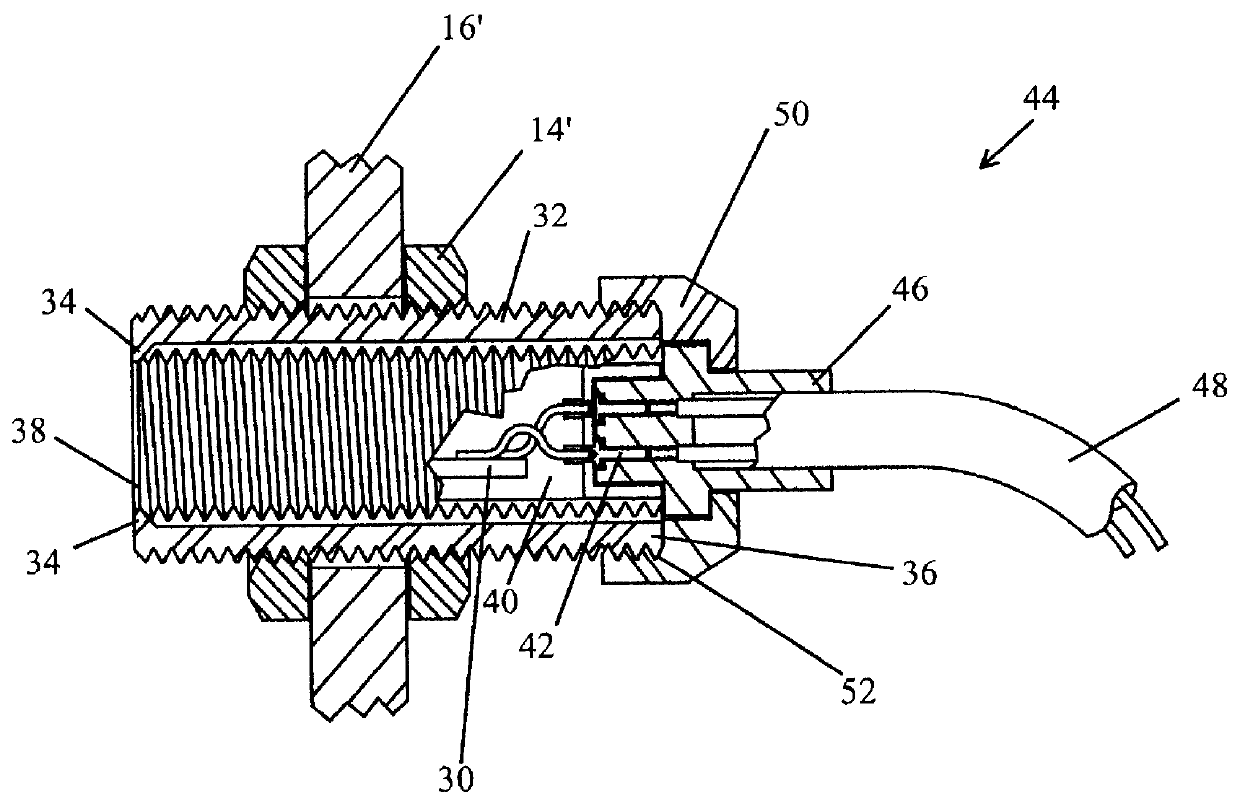
Referring now to FIG. 2 a tubular sensor 30 according to, the present invention is provided with a housing 32 which has a retaining shoulder or lip 34 at one end and a threaded portion 36 at the other. The threads of threaded portion 36 may be extended the full length of housing 32 if desired. The proximity sensing fa...


PUM


Abstract

A mounting for precisely positioning a sensor on an apparatus while allowing removal and replacement without disturbing the precise positioning is shown. A single combination mechanical/electrical connector is used to fix a sensor in its mounting.

Description

This invention relates to the electrical connection and mechanical mounting of manipulating devices on mechanisms. More particularly it relates to a method and apparatus for removably mounting a sensor on a machine in a precise operating position with a single combination electrical / mechanical connector that allows repeated removal and replacement without affecting its precise operating position.BACKGROUND OF INVENTIONModern apparatus of all types increasingly require sensors to be incorporated therein to permit proper manipulation control and operation of the apparatus. Historically this has meant the mechanical positioning of the desired manipulation device in the appropriate position on the apparatus and the electrical connection of the device to the apparatus controller. Apparatus of this type frequently involve movable parts and / or work pieces which sometimes impact the manipulation device sensor destroying its functionality. This has led to the need to quickly remove and repla...

Claims


Application Information

Patent Timeline
IPC IPC(8): H01R13/66H01R13/74
CPCH01R13/6683H01R13/746
Inventor TRUETT, BRETT B.
Owner TRUETT BRETT B
Why Eureka
Try Eureka