
Welding wire spool and drive cartridge

a drive cartridge and wire spool technology, which is applied in the field of wire feeders, can solve the problems of no adjustment, no adjustment, and the interior of the cartridge housing is not easily accessible, and achieves the effect of quick, easy and quick change out, quick, easy and/or efficient manner

Inactive Publication Date: 2006-07-20
LINCOLN GLOBAL INC
View PDF19 Cites 12 Cited by
  • Summary
  • Abstract
  • Description
  • Claims
  • Application Information

AI Technical Summary

Benefits of technology

[0006] The present invention is directed to an interchangeable welding wire cartridge for use in a welding system such as, but not limited to, an electric arc welding system. In accordance with one aspect of the present invention, the welding wire cartridge can be designed to be a) detachably connected to a wire feeder that is integrated in a welding unit, b) detachably connected to a separate wire feeder that is used in conjunction with a welding unit, and / or c) detachably connected to a wire feeder that is on or integrated with a welding gun. The welding wire cartridge is a versatile arrangement that enables a user to easily and quickly change out a source of welding wire on a wire feeder for use in a particular welding operation. As such, the welding wire cartridge enables a user to replace a depleted welding wire source with another source of welding wire in a quick, easy and / or efficient manner. In addition, the welding wire cartridge enables a user to switch out one type of welding wire source for another for use in a particular welding operation in a quick, easy and / or efficient manner.
[0007] In accordance with another and / or alternative aspect of the present invention, the welding wire cartridge includes a cartridge housing designed to be detachably connectable to a wire feeder system. The cartridge housing is typically formed of a durable material (e.g., metal, plastic, reenforced polymers, etc.) so as to withstand the typical environment of a welding system and / or to protect one or more components contained within the cartridge housing. The cartridge housing is configured so that it can be connected to a cartridge housing interface on 1) a stand alone wire feeder and / or a wire feeder integrated in a welder unit, and / or 2) a welding gun and / or wire feeder system integrated with a welding gun. The configuration of the cartridge housing is selected to facilitate in the ease and convenience of connecting and disconnecting the cartridge housing from the cartridge housing interface on the wire feeder. The cartridge housing can include one or more connectors (e.g., tabs, latches, clips, quick-connect, etc.) that facilitate in releasably securing the cartridge housing to the cartridge housing interface on the wire feeder.
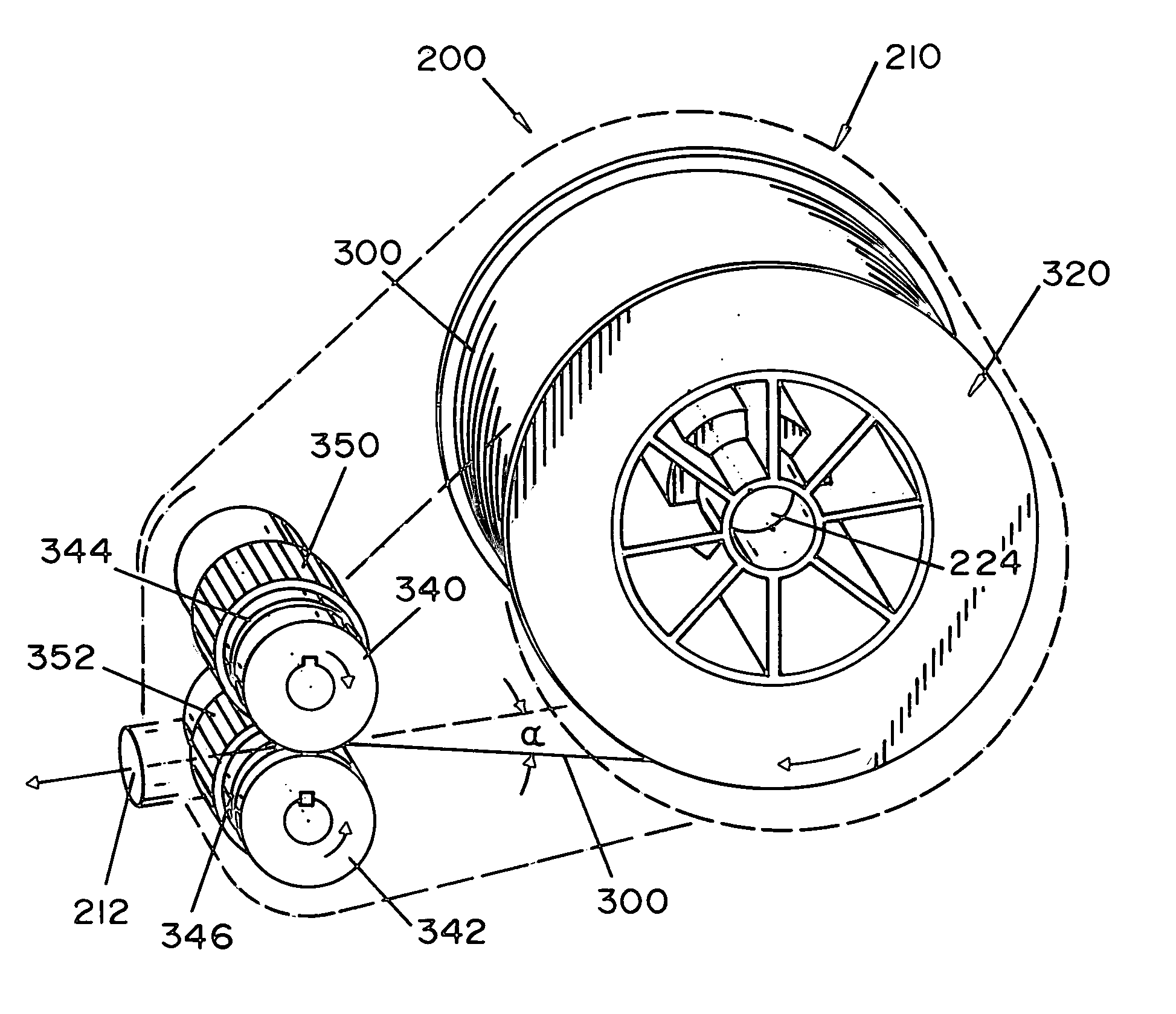
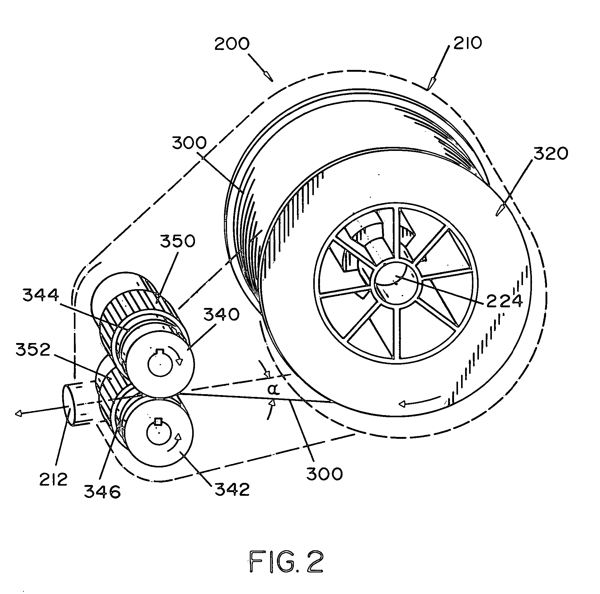
[0008] In accordance with still another and / or alternative aspect of the present invention, the welding wire cartridge includes a wire contact arrangement designed to contact the welding wire and to drive the welding wire at least partially through the welding wire cartridge. In one non-limiting embodiment, the wire contact arrangement includes at least one drive roller. As can be appreciated, other and / or additional configurations can be used. The drive roller can include one or more rough surfaces to facilitate in the gripping of the welding wire so as to reduce slippage of the welding wire. When two drive rollers are used, the drive rollers can be positioned adjacent to one another and rotated in opposite directions to drive the welding wire between the drive rollers. One or both of the drive rollers can include a groove used to guide and maintain the welding wire between the drive rollers as the drive rollers move the welding wire through the welding wire cartridge. As can be appreciated other and / or additional arrangements for the wire contact arrangement can be used. The tension of the wire contact arrangement on the welding wire can be fixed or adjustable. In one non-limiting design, the tension of the wire contact arrangement on the welding wire is preset and fixed so as to ensure that the proper wire tension is applied to the welding wire. The proper tension on the welding wire facilitates in ensuring that the wire contact arrangement properly engages and drives the weld wire, thus reducing or preventing incidences of wire slippage which can adversely affect the feed rate of the welding wire. If the tension is adjustable, the cartridge housing can be designed to enable a user to open and / or access the wire contact arrangement in the cartridge housing, and / or include an adjustment knob, screw, button, etc., that enables a user to adjust the tension on the welding wire without having to open and / or access the interior region of the cartridge housing. In one non-limiting design, the cartridge housing does not allow easy access to the one or more components in the cartridge housing. As such, if any adjustment arrangements are provided on the cartridge housing, which are not required, the adjustment arrangements are accessible from or exposed to the exterior surface of the cartridge housing. In one non-limiting design, the interior of the cartridge housing is not easily accessible and no adjustments are provided. In such a design, the welding wire cartridge is a disposable device designed to be thrown away after the welding wire is fully expended in the cartridge housing. The wire contact arrangement can be partially or fully contained in the cartridge housing.
[0010] In accordance with still yet another and / or alternative aspect of the present invention, the welding wire cartridge can include one or more wire guides designed to at least partially guide the welding wire within the cartridge housing. In one non-limiting arrangement, there is provided a wire guide that at least partially guides the welding wire from the wire contact arrangement to an exterior of the cartridge housing. The wire guide is typically designed to facilitate in the guiding of the welding wire through an opening in the cartridge housing and / or to reduce the incidence of the welding wire kinking or bending as the welding wire is pushed from the wire contact arrangement. In another and / or alternative non-limiting arrangement, there is provided a wire guide that at least partially guides the welding wire as the welding wire is fed to the wire contact arrangement. The wire guide is typically designed to facilitate in the guiding of the welding wire from a welding wire source within the cartridge housing, and / or to reduce the incidence of the welding wire kinking or bending as the welding wire is fed to the wire contact arrangement. In one non-limiting design of the wire guide, the wire guide includes a cylindrically shaped passageway that has an inner diameter that is a little larger than the diameter of the welding wire so as to allow the welding wire to pass through the cylindrically shaped passageway while inhibiting or prevent the welding wire from kinking as it passes through the cylindrically shaped passageway. As can be appreciated, other and / or additional designs of the wire guide can be used. The one or more wire guides can be partially or fully contained in the cartridge housing.
[0021] A further and / or alternative object of the present invention is the provision of a welding wire cartridge that can include a visual identifier to enable a user to easily and / or conveniently identify at least one characteristic of the welding wire cartridge.

Problems solved by technology

In one non-limiting design, the cartridge housing does not allow easy access to the one or more components in the cartridge housing.
In one non-limiting design, the interior of the cartridge housing is not easily accessible and no adjustments are provided.

Method used


Image

  • Welding wire spool and drive cartridge
  • Welding wire spool and drive cartridge
  • Welding wire spool and drive cartridge

Examples


Embodiment Construction

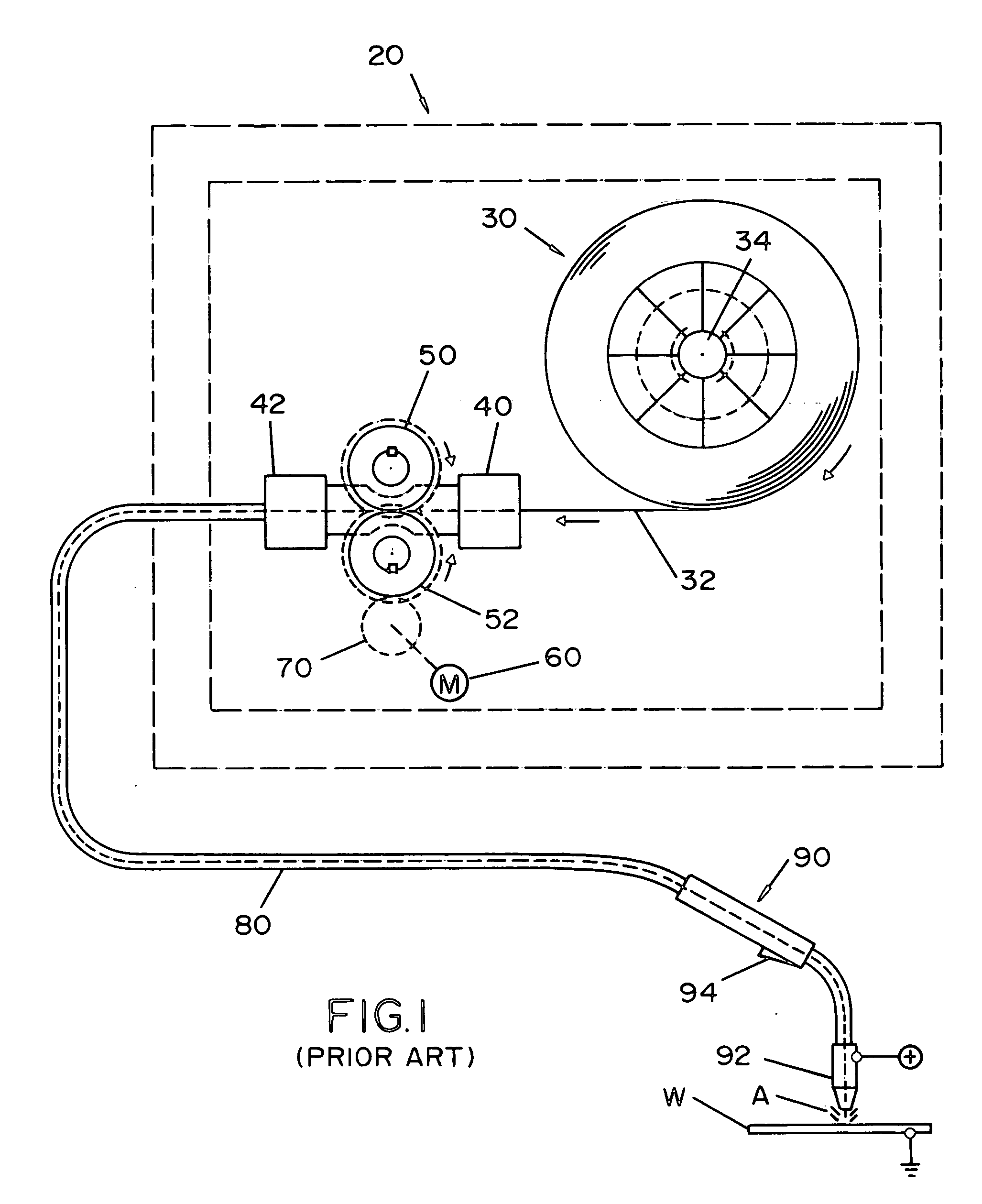
[0030] Referring now to the drawings, wherein the showings are for the purposes of illustrating the preferred embodiments of the invention only and not for the purpose of limiting the same, FIG. 1 illustrates a prior art wire feeder 20. Prior art wire feeder 20 is representative of a wire feeder integrated in a welding unit, not shown, such as, but not limited to, the Power MIG 225 offered by The Lincoln Electric Company, or a stand alone wire feeder that is used in conjunction with a welding unit, not shown, such as, but not limited to, the LF-72 Wire Feeder offered by The Lincoln Electric Company; however, the wire feeder is not limited to these two models of welding units or stand alone wire feeders.

[0031] Stand alone or integrated wire feeder 20 includes a reel or spool 30 of welding wire 32 rotatably positioned on a spindle 34. The welding wire 32 is fed into a wire guide 40 that directs the welding wire to drive rollers 50, 52. A motor 60 causes the drive rollers to rotate in...


PUM

PropertyMeasurementUnit
lengthaaaaaaaaaa
angleaaaaaaaaaa
angleaaaaaaaaaa

Abstract

A modular welding wire cartridge for use in a welding system. The welding wire cartridge is designed to be detachably connected to the welding wire feed system of the welding system. The welding wire cartridge includes a drive housing designed to be detachably connectable to the welding wire feed system, a wire contact arrangement designed to controllably feed welding wire through the welding wire cartridge, and a spool of welding wire.

Description

[0001] The present invention is related to the art of welding and more particularly to welders that include the use of wire feeders and even more particularly to welding wire sources for wire feeders. BACKGROUND OF THE INVENTION [0002] Wire feeders for electric arc welders typically include a welding wire drive assembly that pulls welding wire from a welding wire source (e.g., wire spool, canister of wire, etc.) and then feeds the welding wire to the welding gun. The wire drive assembly typically includes one or more drive wheels that pull and push the welding wire at a desired or controlled wire feed speed so that the proper amount of molten metal is deposited on a workpiece during the formation of a weld bead or the like. [0003] The wire feeder for many types of welding operations is either connected to or integrated with the welder. The wire feeder includes an integrated motor, drive rollers, gears, and wire guides designed to draw the welding wire from a welding wire source and ...

Claims


Application Information

Patent Timeline
Patent Type & Authority Applications(United States)
IPC IPC(8): B23K9/10
CPCB23K9/1336
Inventor DIEKMANN, CRAIG L.NELSON, BRYAN J.
Owner LINCOLN GLOBAL INC
Learn More