Solar energy collector system

a solar energy collector and solar energy technology, applied in the direction of solar heat collectors for particular environments, solar radiation concentration, moving/orienting solar heat collectors, etc., can solve problems such as shading, and achieve the effect of reducing collector efficiency and avoiding complexity

Inactive Publication Date: 2000-10-17
AREVA SOLAR
View PDF19 Cites 121 Cited by
  • Summary
  • Abstract
  • Description
  • Claims
  • Application Information

AI Technical Summary

Benefits of technology

The collector system of the present invention permits the use of a drive system which is simpler than that disclosed in International Patent Application No. PCT / AU96 / 00177. That is, all or, at least, the majority of the reflectors may be coupled together, and this avoids the complexity that is inherent in a drive system which is required to act on individual reflectors and to effect a shift in the reflected radiation from one receiver system to the other. It is possible that the collector system of the present invention may not always avoid completely the effects of shading, but any reduction in collector efficiency that arises from the existence of some shading is offset by the benefits that flow from the use of a relatively simple reflector drive system.

Problems solved by technology

However, a problem that is inherent in the use of ground arrayed reflectors is that shading occurs as a consequence of radiation blockage.

Method used


Image

  • Solar energy collector system
  • Solar energy collector system
  • Solar energy collector system

Examples


Embodiment Construction

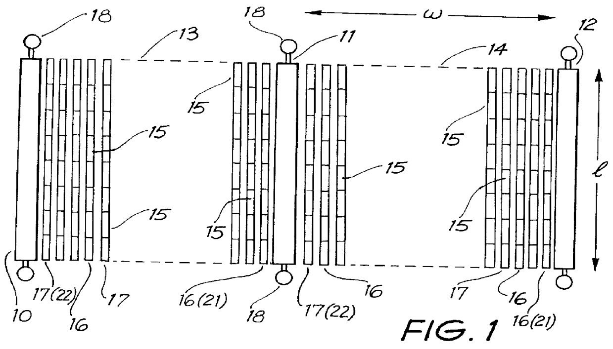
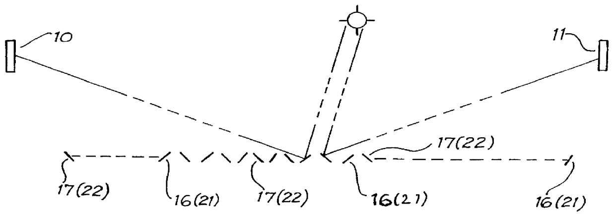
As illustrated in FIG. 1, the solar collector system incorporates three spaced-apart, parallel receiver systems 10, 11 and 12 which are separated by two reflector groups 13 and 14. Each of the reflector groups comprises an array of reflectors 15 positioned in parallel rows 16 and 17, and the reflector groups 13 and 14 are disposed to reflect incident radiation to one or the other of the adjacent receiver systems 10, 11 or 12. That is, as shown in FIG. 2, the reflectors 15 in rows 16 of the first group 13 are orientated to reflect incident radiation to the receiver system 10, whilst those in rows 17 of the first group 13 are orientated to reflect incident radiation to the receiver system 11. Similarly, the reflectors 15 in rows 16 of the second group 14 are orientated to reflect incident radiation to the receiver system 11, whilst the reflectors in rows 17 of the same group 14 are orientated to reflect incident radiation to the receiver system 12.

Each of the receiver systems has a le...


PUM


Abstract

PCT No. PCT / AU97 / 00864 Sec. 371 Date Jun. 18, 1999 Sec. 102(e) Date Jun. 18, 1999 PCT Filed Dec. 19, 1997 PCT Pub. No. WO98 / 28579 PCT Pub. Date Jul. 2, 1998A solar energy collection system which includes n groups (13, 14) of arrayed reflectors (15) and n+1 target receiver systems (10, 11, 12) which represent absorbing surfaces to solar radiation that is reflected by the reflectors (15). The receiver systems (10, 11, 12) are elevated relative to the reflectors (15) and the reflectors are pivotally mounted to support structures (19) in a manner such that they may be positioned angularly to reflect incident radiation (I1, I2) toward one or the other of the receiver systems (10, 11, 12). The collector system is characterized in that a majority at least of the reflectors (15) within each group (13, 14) are arranged to be driven simultaneously to pivot through the same angle (+526 ), in that the reflectors (15) within each group (13, 14) are arrayed in two sub-groups (21 and 22), and in that a majority at least of the reflectors (15) within the respective sub-group (21 and 22) are oriented permanently toward respective ones of the receiver systems (10, 11, 12).

Description

This invention relates to a solar energy collector system and, in particular, to a system which includes receivers which function to absorb solar radiation and reflectors which are arranged to reflect incident solar radiation toward the receivers. The invention is hereinafter described largely in the context of a collector system which employs receivers that incorporate evacuated tube-type collector elements which function to convert the energy content of incident solar radiation into thermal energy and to transfer the thermal energy to heat exchange fluid. However, it will be understood that the invention does have broader application, for example to systems which include receivers in the form of inverted cavity collectors and photovoltaic cells.A collector system of the type with which the present invention is concerned is referred to as a Fresnel reflector system and, depending upon its configuration, may be considered as an analogue of a parabolic dish or a linear parabolic trou...

Claims


Application Information

Patent Timeline
Patent Type & Authority Patents(United States)
IPC IPC(8): F24J2/10F24J2/06F24J2/07F24S20/20F24S23/70
CPCF24J2/07F24J2/10F24J2/541F24J2002/1076Y02E10/47Y02E10/41Y02B10/20F24S23/70F24S20/20F24S30/425F24S2023/872F24S2023/87Y02E10/40
Inventor MILLS, DAVID
Owner AREVA SOLAR
Why Eureka
Try Eureka