Wellbore tubular patch system

a tubular patch and wellbore technology, applied in the field of stroke indicators, can solve the problems of hardly perfect seals, cracks between, and leaks between casings and liner, and achieve the effect of avoiding leaks and avoiding leaks

Inactive Publication Date: 2000-11-07
WEATHERFORD TECH HLDG LLC
View PDF60 Cites 233 Cited by
  • Summary
  • Abstract
  • Description
  • Claims
  • Application Information

AI Technical Summary

Benefits of technology

The system may have a sleeve shear pinned at the top of the body so that a top nose cone does not prematurely enter the liner. The pins are sheared following correct deployment of the collet fingers by pulling on the system.
Such a system which prevents premature cone entry into a liner to be expanded; and

Problems solved by technology

Occasionally, a leak develops at some point in the casing and permits the loss of well fluids to a low pressure, porous zone behind the casing, or permits an unwanted fluid such as water to enter the well.
Such seals are seldom perfect.
As a result, if the pressure of fluids from the formations penetrated by the well is applied to the outside of the liner and casing, a leak usually results.
When pressure is applied outside the liner and casing, the liner is compressed more than the casing and a crack forms between them even if none existed before.
Since the wider the opening, the more the casing stress is relieved and since the more this stress is relieved, the wider the opening becomes, it is apparent that a leak between the casing and liner can hardly be avoided even though a long overlap of casing and liner is provided.
This problem is particularly acute if it is desired to place a steel liner or patching steel sleeve over parted casing or a split or hole in casing.
In this case, it is difficult to place Portland cement between the casing and liner and hold the cement in place until it sets.
In addition, the application of pressure outside the liner quickly causes leakage in the manner just described.
A difficulty encountered in utilizing liner expanding tools in casing or production tubing is in removing the tool after the tool has been driven through the liner.
If there are restrictions in the diameter of the pipe in or above the area covered by the expanded liner, there is more likelihood that the tool may hang up at the restriction and possibly even damage the liner as it is pulled therethrough.
This method of placing the liner sometimes presents problems which contribute significantly to the expense of the operation.
One problem is that the tubing string must be pulled and run in the well twice, once to attach the sleeve and setting tool and once to remove the setting tool.
Another problem is that weak sections in the tubing sometimes fail under the force of the hydraulic pressure used to operate the expander.
A system as shown in FIG. 1A permits limited expansion and contraction of its collet assembly and is not suitable as a "thru-tubing" system or a system to be run through a first relatively small tubular into a relatively larger tubular to be repaired.
Often such welding can present a safety hazard.
Also the shipment of relatively longer tubular patches from the factory to a rig site is usually not practical or economical.

Method used


Image

  • Wellbore tubular patch system
  • Wellbore tubular patch system
  • Wellbore tubular patch system

Examples


Embodiment Construction

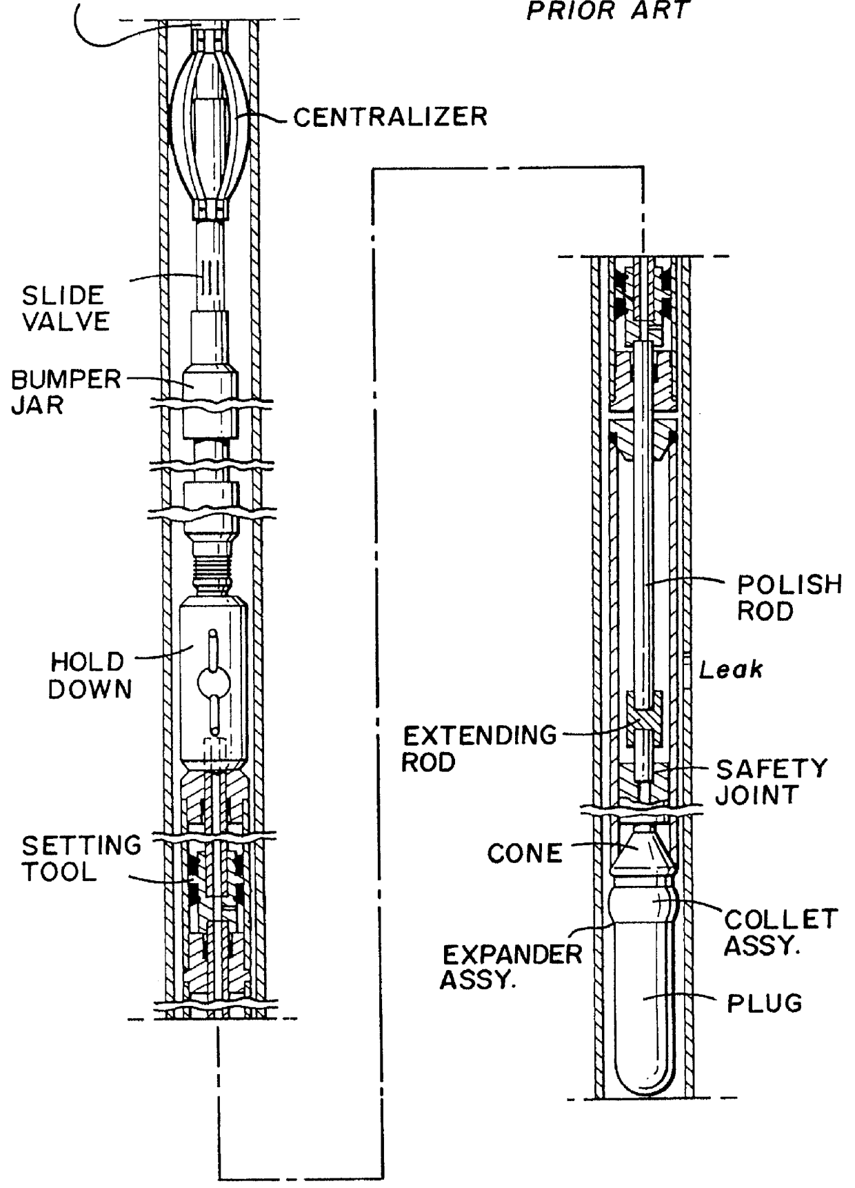
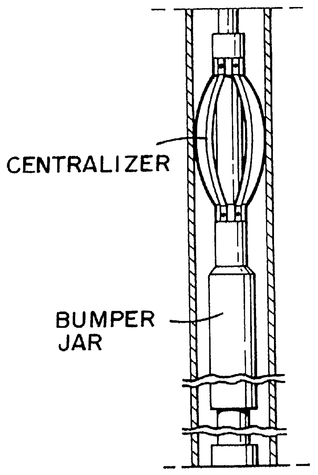
FIGS. 2A shows a system 10 according to the present positioned beneath a liner casing patch P in a cased wellbore (not shown, like the casing in FIG. 1A) prior to movement of the system 10 through the liner patch P. The system 10 may include (and does in this particular aspect) the items and apparatuses above the cone of the system of FIG. 1A and the description of them is repeated here.

FIG. 2B shows the system 10 with collet fingers 52 and 92 moved and held outwardly. FIG. 2C shows the cone 11 after it has begun its entry into the liner patch P.

FIG. 3A shows parts of the system 10 according to the present invention as shown in FIG. 2A. The system 10 has a cone 11 initially disposed in a sleeve 12 which itself is shear pinned with three shear pins 13 (two shown) to a piston housing 22. The cone 11 has a shaft 14 threadedly engaged in a recess 23 of the piston housing 22. A shoulder 15 of the cone 11 rests initially against a shoulder 16 of the sleeve 12. An upper end 17 of the sleev...


PUM


Abstract

A wellbore tubular patch for patching a hole in a wellbore has been invented, the tubular patch in certain aspects having an expandable top member having a hollow tubular body and a top end and a bottom end, an expandable bottom member having a hollow tubular body and a top end and a bottom end, an expandable outer sleeve in which is secured a portion of the bottom end of the expandable top member, and a portion of the top end of the expandable bottom member inserted into and held within expandable outer sleeve. A method for making a tubular patch for patching a hole in a tubular in an earth wellbore has been invented, the method in certain aspects including securing a portion of a bottom end of an expandable top member in an expandable outer sleeve, the expandable top member having a hollow tubular body and a top end, and securing a portion of a top end of an expandable bottom member within the expandable outer sleeve, the expandable bottom emmber having a hollow tubular body.

Description

1. Field of the InventionThis invention is directed to a stroke indicator for wellbore apparatus with an inner movable mandrel and for systems for patching a hole or leak in a tubular member in a wellbore; to such systems that expand a liner patch to create a seal; to methods for using such systems; to a two-member tubular patch; and, in one particular aspect, to such a system and methods of its use that can be inserted through a relatively small diameter restriction as is presented by some types of tubing and then into a larger diameter member that has an area to be sealed.2. Description of Related ArtOil and gas wells are ordinarily completed by first cementing casing in the hole. Occasionally, a leak develops at some point in the casing and permits the loss of well fluids to a low pressure, porous zone behind the casing, or permits an unwanted fluid such as water to enter the well.It is sometimes necessary to patch a hole or other defect in oil well pipe such as casing or product...

Claims


Application Information

Patent Timeline
Patent Type & Authority Patents(United States)
IPC IPC(8): E21B29/10E21B29/00E21B17/02E21B17/08E21B43/02E21B43/10E21B47/00E21B47/09F16L55/163F16L55/162
CPCE21B17/02E21B17/08E21B29/10E21B47/091E21B43/105E21B43/106E21B43/103E21B47/095
Inventor SMALLEY, MICHAEL T.BAILEY, THOMAS R.WRIGHT, RALPH D.HAUGEN, DAVID M.TILTON, FREDERICK T.
Owner WEATHERFORD TECH HLDG LLC
Why Eureka
Try Eureka