
Fiber connector and adaptor

a technology of fiber optic connectors and adapters, which is applied in the direction of optics, instruments, optical light guides, etc., can solve the problems of limiting the density of fiberoptic connectors, terminal ends that receive such connectors are susceptible to impact damage, and exposed interior elements of adapters

Inactive Publication Date: 2000-11-07
COMMSCOPE TECH LLC
View PDF33 Cites 173 Cited by
  • Summary
  • Abstract
  • Description
  • Claims
  • Application Information

AI Technical Summary

Problems solved by technology

Further, adapters which received such connectors presented exposed interior elements.
As a result, such terminal ends would be susceptible to impact damage or the like.
Further, light transmitted through the optical fiber could inadvertently be directed into the eye of a technician or other person viewing the optical fiber or adapter.
However, the manner in which such functions are achieved restricts the density of fiberoptic connectors.

Method used


Image

  • Fiber connector and adaptor
  • Fiber connector and adaptor
  • Fiber connector and adaptor

Examples


Embodiment Construction

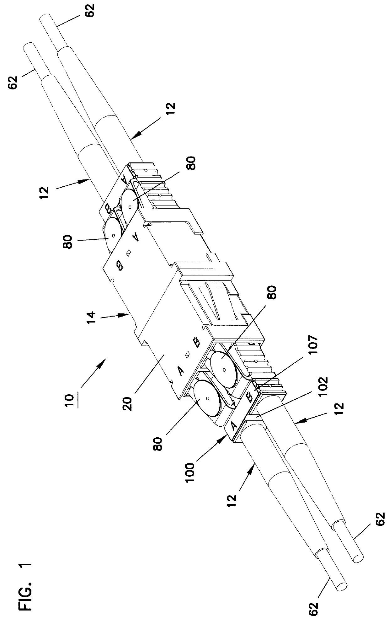
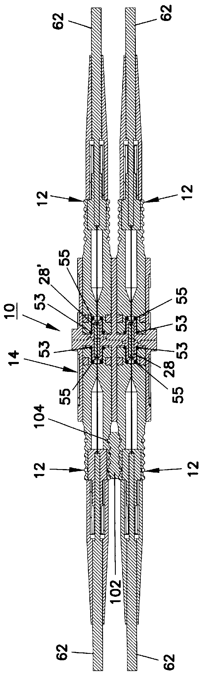
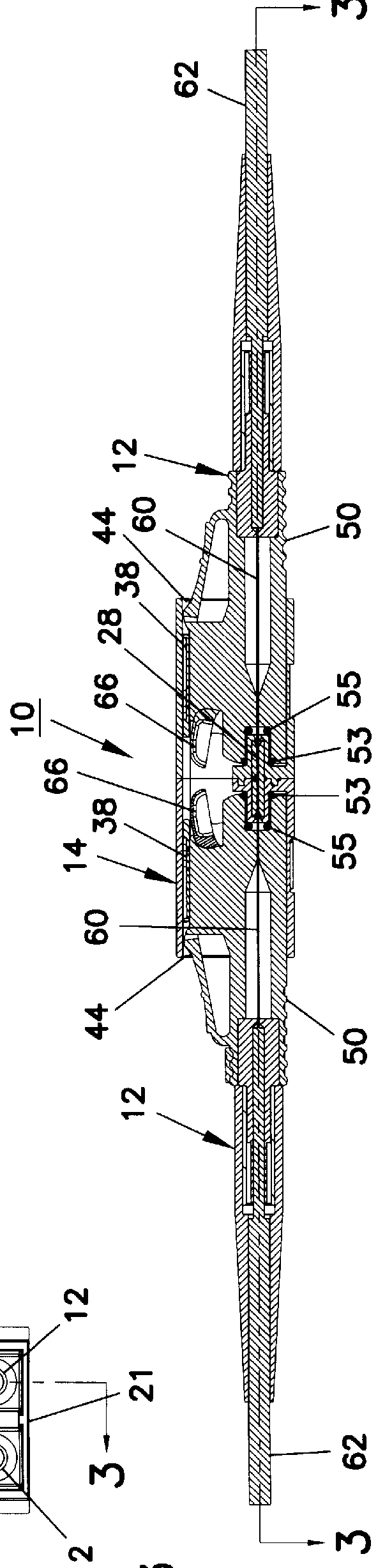
With initial reference to FIGS. 1-4, a connector / adapter assembly 10 is shown including four fiberoptic connectors 12 (each of identical construction) contained within a single adapter 14. The external geometry of the adapter 14 is the same as that shown in U.S. Pat. No. 5,317,663. In other words, the cross sectional area of the adapter 14 is identical to that of a standard SC adapter such as that shown in U.S. Pat. No. 5,317,663 so that the adapter 14 may be inserted into preexisting applications which received the prior SC adapter of U.S. Pat. No. 5,317,663.

The adapter 14 is separately shown in FIGS. 17-20 to which attention is now directed. The adapter 14 includes two halves 16, 16' joined at a flange 18. The flange 18 may be placed within a sheet metal support so that multiple adapters 14 can be positioned in side-by-side alignment on a sheet metal panel. Preferably, when the halves 16, 16' are joined, the part line between the halves 16, 16' is ultrasonically welded (or epoxied...


PUM


Abstract

Fiberoptic connector and adapter assembly includes a fiberoptic connector received within an adapter. The connector has a cover on the connector housing. The cover pivots between open and closed positions to expose or cover, respectively, a optical fiber contained within the connector. Longitudinal guides of the connector are received cooperating with longitudinal guides of the adapter to direct the connector into the adapter in a prescribed alignment. A cam pin is carried on the adapter to engage a cam pin receiving slot on the cover to urge the cover to the open position as the connector is inserted into the adapter. A spring mechanism biases the cover toward the closed position and open positions.

Description

II. BACKGROUND OF THE INVENTION1. Field of the InventionThis invention pertains to connectors and adapters for optical fibers. More particularly, this invention pertains to such connectors and adapters which include end caps for covering an end of the connector or adapter when the connector is not inserted into a mating adapter.2. Description of the Prior ArtFiberoptic connectors historically presented exposed ends. Further, adapters which received such connectors presented exposed interior elements. The exposed ends and interior elements included the terminal ends of optical fibers. As a result, such terminal ends would be susceptible to impact damage or the like. Further, light transmitted through the optical fiber could inadvertently be directed into the eye of a technician or other person viewing the optical fiber or adapter.The prior art has developed end caps for covering optical fibers when a connector is not in use. An example of such is shown in U.S. Pat. No. 5,348,487 to M...

Claims


Application Information

Patent Timeline
IPC IPC(8): G02B6/38
CPCG02B6/3807G02B6/3825G02B6/3849G02B6/3893G02B6/3878G02B6/00
Inventor LU, LIANG-JU
Owner COMMSCOPE TECH LLC
Features
  • Generate Ideas
  • Intellectual Property
  • Life Sciences
  • Materials
  • Tech Scout
  • Unparalleled Data Quality
  • Higher Quality Content
  • 60% Fewer Hallucinations
Learn More