Stereoscopic camera

a stereoscopic camera and camera body technology, applied in the field of stereoscopic cameras, can solve the problems of increased loss in the photographing area in the case, change in the solid effect, and difficulty in determining the position of mounting the slides

Inactive Publication Date: 2000-11-07
INABA MINORU
View PDF23 Cites 14 Cited by
  • Summary
  • Abstract
  • Description
  • Claims
  • Application Information

AI Technical Summary

Problems solved by technology

Therefore, many kinds of stereo slide mounts are necessary having different window widths depending upon the distant view and the close-range view and, particularly, loss increases in the photographing areas in the case of the close-range view.
Moreover, parallax varies depending upon a positional relationship of the right and left slides that are mounted, resulting in a change in the solid effect, which makes it very difficult to determine the positions for mounting the slides.
However, the following inconvenience arises since optimum interoptical distance is not obtained with respect to subjects other than the one on which a focal point is set.
When the mount is brought to the developing laboratory, therefore, the distance for mounting the pair of right and left slides may not be often that of a desired distance and satisfactory stereo effect will not be obtained.

Method used


Image

  • Stereoscopic camera
  • Stereoscopic camera
  • Stereoscopic camera

Examples


Embodiment Construction

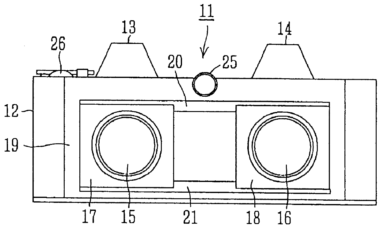
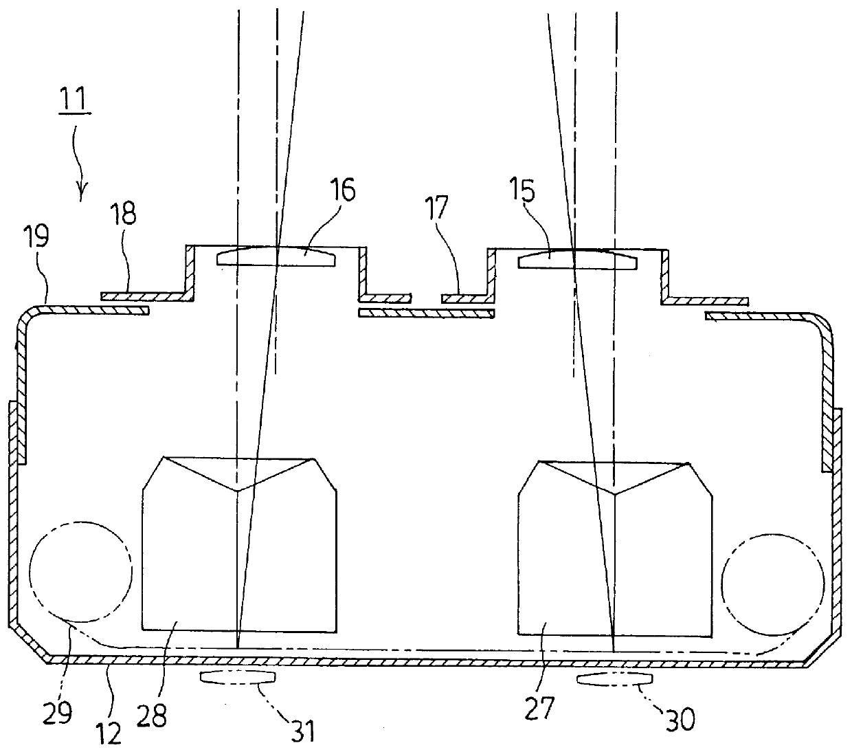
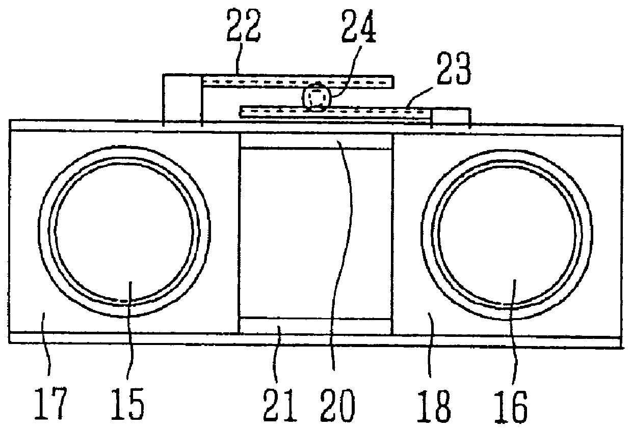
An embodiment of the present invention will now be described in detail with reference to the drawings 1 to 11. FIGS. 1 and 2 illustrate a stereoscopic camera 11 which has two reflex finders 13, 14 and two photographing lenses 15, 16 that are assembled in a camera body 12 just in a structure in which two single-lens reflex cameras are coupled together in parallel. The photographing lenses 15 and 16 are mounted on lens mount plates 17 and 18. Referring to FIG. 3, the lens mount plates 17 and 18 are engaged with guide rails 20 and 21 that are arranged in the right-and-left direction in a front slide frame 19 of the stereoscopic camera 11. Racks 22 and 23 are provided at upper portions of the lens mount plates 17 and 18 in parallel with the guide rails 20 and 21, and toothed surfaces of the two racks 22 and 23 are facing each other. A pinion gear 24 supported by the front slide frame 19 is arranged between the two racks 22 and 23 and is in mesh with the upper and lower racks 22 and 23. ...


PUM


Abstract

A stereoscopic camera for stereoscopic photography, which reduces losses in the screen when taking a picture in a close range and provides optimum stereoscopic effect without the need of adjusting the distance between the slides that are being mounted. A camera body is furnished with reflex finders constituted by a pair of right and left photographing lenses and pentaprisms. The distance between optical axes of the photographing lenses is adjusted by a horizontal shifting mechanism. Focusing plates of the right and left finders are marked with vertical lines at the centers and on the right and left sides thereof. The distance between optical axes is adjusted depending upon the distance to the subject and vertical lines of the right and left focusing plates are brought into agreement. Then, the right and left photographing areas are nearly brought into agreement on the real screen and no loss occurs on the screen.

Description

The present invention relates to a stereoscopic camera and, particularly, to a stereoscopic camera equipped with a parallax correction function.DESCRIPTION OF THE PRIOR ARTA stereoscopic camera simultaneously takes two pieces of a picture using two photographing lenses that are spaced apart in the right-and-left direction. A set of two pieces of slides in which a picture is taken using a reversal film are fitted on a stereo slide mount, and a viewer enjoys watching a solid picture using a stereo slide viewer.Two photographing lenses of the stereoscopic camera are so mounted that the optical axes thereof are in parallel, and parallax takes place on the two pieces of slides 1L and 1R on which a picture is taken simultaneously as shown in FIG. 12 due to a distance between the optical axes of the two photographic lenses. As shown in FIG. 12, furthermore, the two pieces of slides 1L and 1R are fitted on a stereo slide mount 2, and the slide of the left side is viewed by the left eye and ...

Claims


Application Information

Patent Timeline
Patent Type & Authority Patents(United States)
IPC IPC(8): G03B35/10G03B35/00G03B13/14
CPCG03B35/10G03B35/00
Inventor INABA, MINORU
Owner INABA MINORU
Why Eureka
Try Eureka