Method and apparatus for retaining a cable in a conduit

a technology of cable assembly and conduit, applied in the direction of cables, insulated conductors, borehole/well accessories, etc., can solve the problems of general inability to support their own weight, difficulty in retaining cable assemblies, danger,

Inactive Publication Date: 2000-11-14
CAMCO INT
View PDF14 Cites 61 Cited by
  • Summary
  • Abstract
  • Description
  • Claims
  • Application Information

AI Technical Summary

Problems solved by technology

Power and data cables, which are generally incapable of supporting their own weight over the considerable depth of most wells, are secured to the suspension cables.
In coiled tubing deployed systems, difficulties arise in retention of cable assemblies in the coiled tubing during various phases of installation, use and servicing.
Both during initial installation and subsequent servicing of coiled tubing deployed pumping systems, a danger exists that the cable will withdraw into the conduit.
During servicing, as the cable is disconnected from above-ground equipment, a similar risk of relaxation and withdrawal exists.
In either case, once a cable end is lost within the conduit, a time consuming and expensive retrieval operation is required to extract the cable before normal service can be resumed.

Method used


Image

  • Method and apparatus for retaining a cable in a conduit
  • Method and apparatus for retaining a cable in a conduit
  • Method and apparatus for retaining a cable in a conduit

Examples


Embodiment Construction

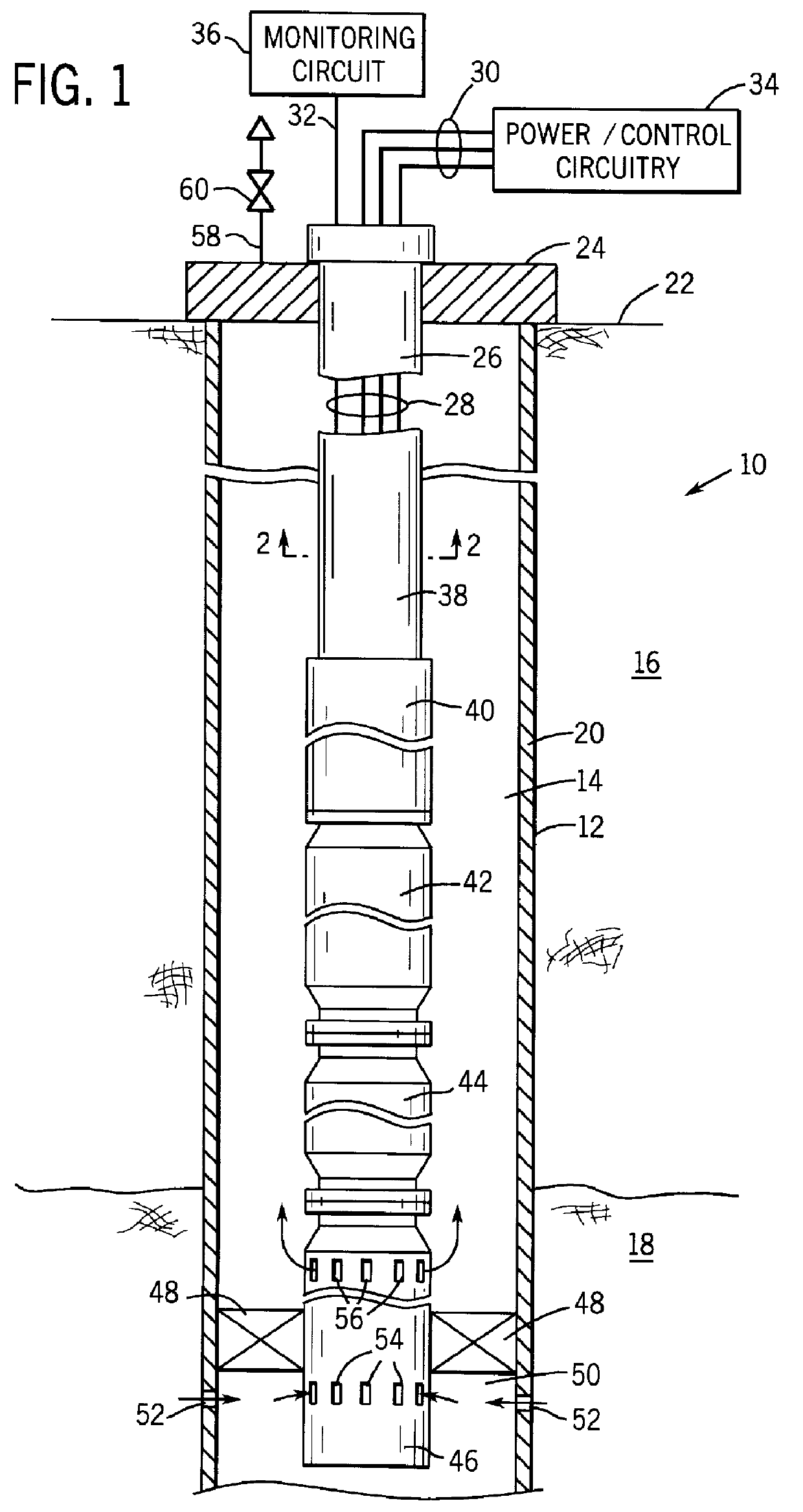
Turning now to the drawings, and referring first to FIG. 1, a section of powered well equipment is illustrated in the form of an electrical submersible pumping system 10 deployed in a well 12. Well 12 forms a wellbore 14 which traverses a series of subterranean formations 16, and a production formation 18. Such production formations will typically bear fluid deposits of economic interest, such as oil, gas, paraffin, and the like. A casing 20 surrounds the peripheral walls of wellbore 14 to maintain stability of the wellbore through the formations. Well 12 extends to the production formations from the earth's surface as indicated at reference numeral 22.

While the arrangement illustrated in FIG. 1 is provided by way of example, it should be noted that the techniques described herein may be employed with various types of equipment and well configurations. Accordingly, these techniques may be employed with powered pumping systems, as well as production equipment, completion equipment, i...


PUM


Abstract

A technique is provided for retaining a cable assembly in a length of conduit, such as coiled tubing. The retaining assembly is secured to an end of the coiled tubing and to tensile members of the cable assembly. A retainer element may be secured directly to conductors of the cable assembly for holding the cable assembly adjacent to the retaining structure. The retainer may include a flat plate-like structure which abuts against a surface of the assembly, such as against an upper surface of a connector to prevent re-entry of the cable into the coiled tubing. Following attachment of the cable and coiled tubing, the submersible equipment coupled to the coiled tubing may be retracted or withdrawn from the well. Certain of the conductors may be coupled to monitoring circuitry for continuously monitoring well parameters during such repositioning. The technique may be used during initial installation of coiled tubing deployed systems, or during subsequent removal or servicing of the equipment.

Description

1. Field of the InventionThe present invention relates to the field of cable assemblies for use with electrical equipment such as submersible pumping systems in petroleum wells. More particularly, the invention relates to a technique for retaining a cable assembly in a conduit during installation, use and servicing.2. Description of the Related ArtA number of applications exist for electrical cable assemblies deployed within conduits. In submersible pumping systems, for example, cable assemblies extending from the earth's surface convey power to electrical equipment. The powered equipment typically includes electric motors used to drive pumps and other system components, parameter detection and measurement devices, control circuitry, data storage and transfer devices and so on. At the earth's surface the cable assemblies are coupled to power sources, such as generator sets, and to interface circuitry for the data acquisition and control of the submerged components.In well applicatio...

Claims


Application Information

Patent Timeline
Patent Type & Authority Patents(United States)
IPC IPC(8): E21B33/03E21B33/04E21B17/00
CPCE21B33/0407E21B17/003
Inventor KOBYLINSKI, LEE S.
Owner CAMCO INT
Why Eureka
Try Eureka