Fluid operated gripper device

a gripper and fluid-operated technology, applied in the direction of manipulators, load-engaging elements, conveying parts, etc., can solve the problems of difficult miniaturization and still somewhat elaborate structure of the gripper, and achieve the effect of compact dimensions and simple manufactur

Inactive Publication Date: 2000-11-14
FESTO AG & CO KG
View PDF10 Cites 23 Cited by
  • Summary
  • Abstract
  • Description
  • Claims
  • Application Information

AI Technical Summary

Benefits of technology

One object of the invention is to create a gripper device of the type initially mentioned, which renders possible simpler manufacture and more compact dimensions.
FIGS. 5 and 6 show the gripper device of FIG. 4 in a side elevation together with a modified form of suitable attachment means, which render possible an attachment to a gripper device carrier.

Problems solved by technology

However its structure is still somewhat elaborate and is more particularly it is hard to miniaturize it further.

Method used


Image

  • Fluid operated gripper device
  • Fluid operated gripper device
  • Fluid operated gripper device

Examples


Embodiment Construction

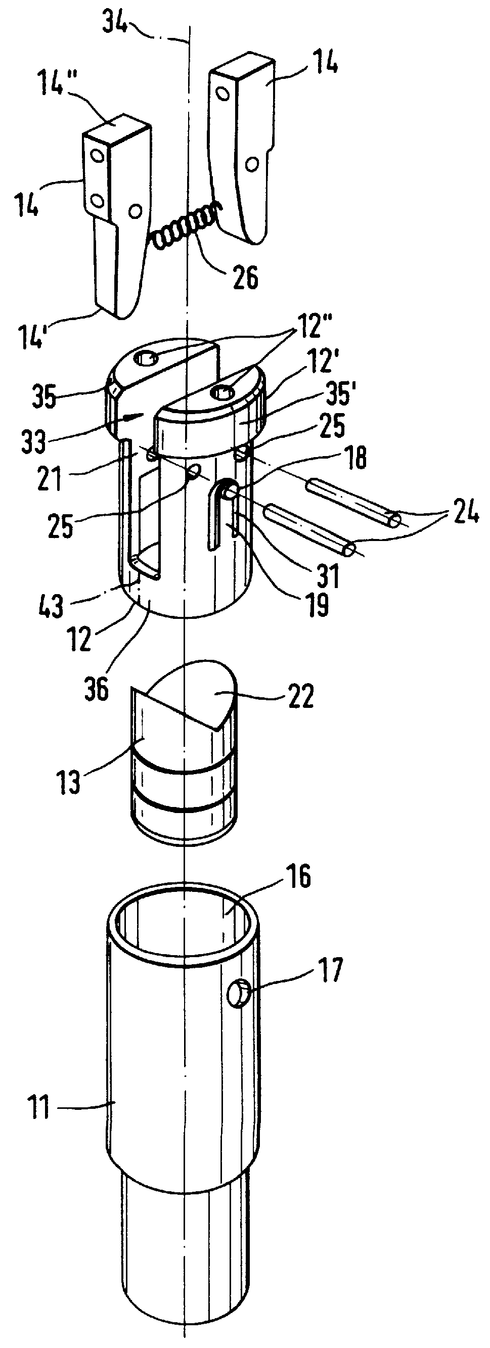
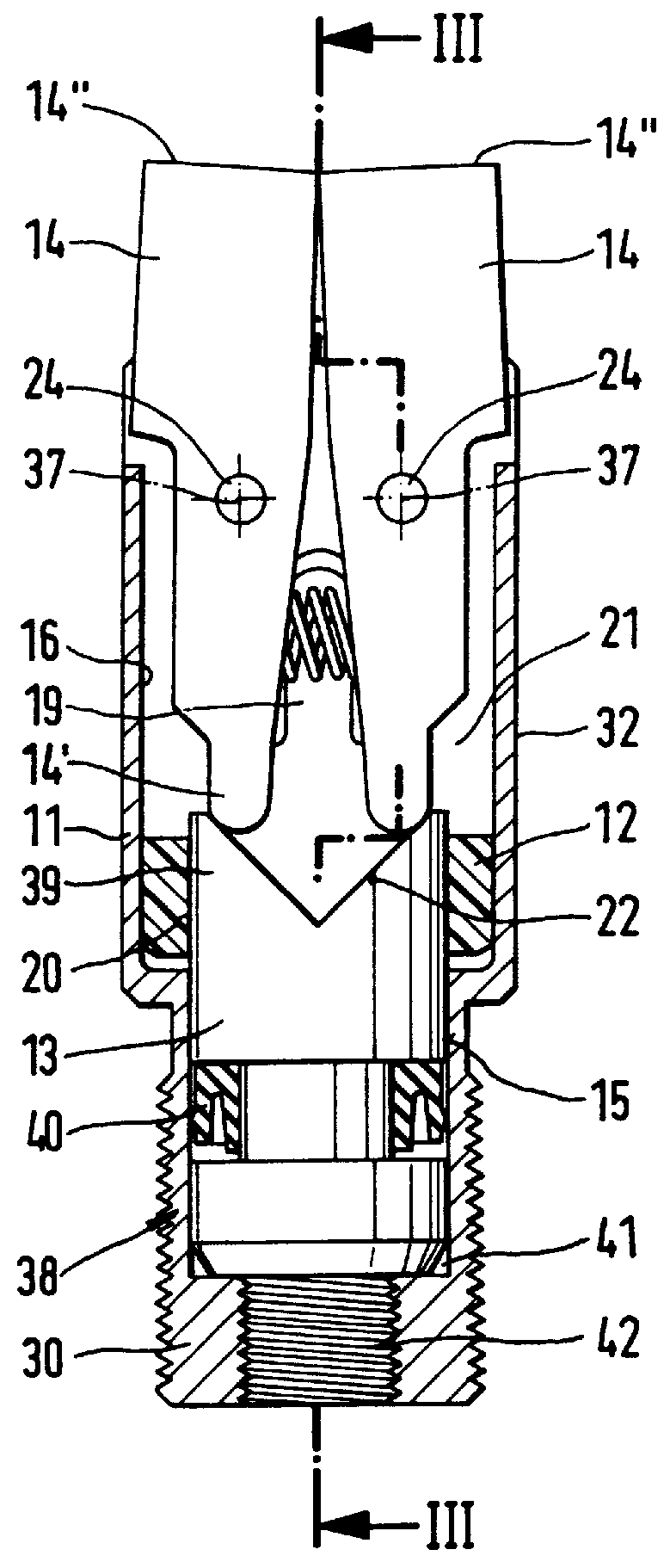
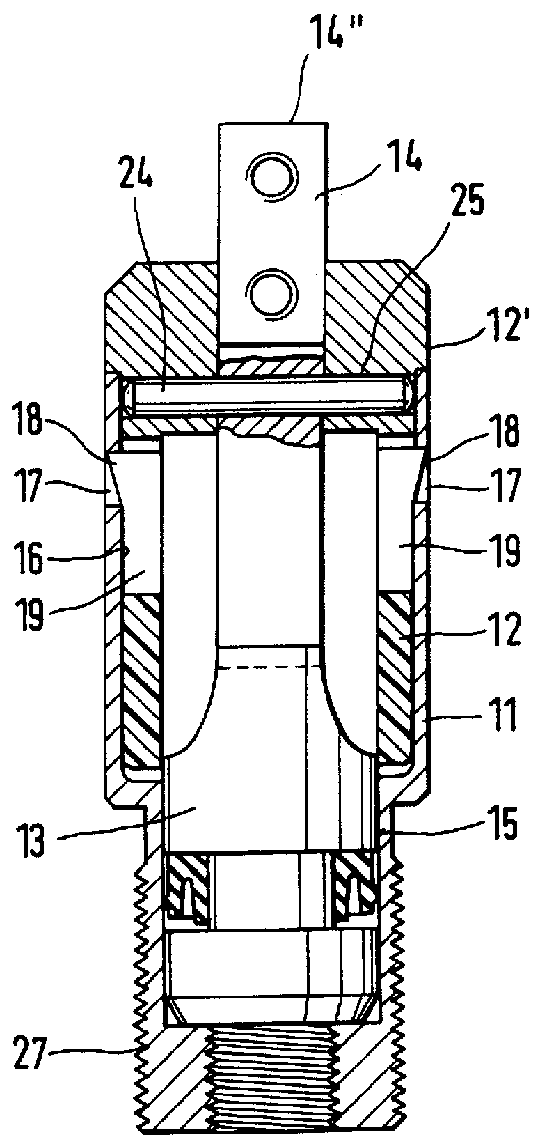
The gripper devices in accordance with the present embodiment are operated pneumatically using compressed air. They respectively comprise a gripper device housing 11, an insert body 12 serving as a bearing body for two gripping device jaw carriers 14 and a piston 13 serving for operation of the gripper device jaw carrier 14.

The gripper device housing 11 is designed like a hollow body and in the present embodiment of the invention possesses a single or multiply stepped cylindrical external. shape. It delimits axially extending internal space, which is divided up into two axially sequentially and preferably directly coaxially merging chambers, that is to say a piston chamber 15 and a receiving chamber 16. The receiving chamber 16 is open at a front axial side of the gripper housing 11. The piston chamber 15 adjoins it at the rear side of the gripper device housing 11 and functionally at the rear axial side is delimited by a terminating wall 30 of the gripper device housing 11. The dia...


PUM


Abstract

A fluid operated gripper which possesses a gripper device housing resembling a hollow body and on which a bearing body is secured. On the bearing body at least two relatively moving gripper device jaw carriers are movably mounted in a slot arrangement. A drive piston runs in a piston chamber. The bearing body is designed in the form of an insert body, which is seated like a cartridge in a receiving chamber arranged in an axial extension of the piston chamber. The slot arrangement is overlapped to the side externally by the housing wall, which delimits the receiving chamber, for at least part of its length.

Description

The invention relates to a fluid operated gripper device comprising a gripper housing designed like a hollow body on which a bearing member is secured, on which in a slot arrangement consisting of one or more slots at least two gripper device jaw carriers are movably mounted, said carriers being able to be moved between an open position and a closed position in relation to one another, and an actuating element able to be shifted between two positions for causing movement of the gripper jaw carriers, shift of said actuating element in at least one direction being caused by operation of a piston running in a piston chamber.THE PRIOR ARTA gripper device of this type, which is designed in the form of a so-called angle gripper device, is disclosed in a brochure entitled "Greifer--die Handhabung im Griff" (gripper devices--getting to grips with handling), page 3, published by the assignee. This gripper device comprises a housing resembling a hollow body, in which a piston runs and from wh...

Claims


Application Information

Patent Timeline
Patent Type & Authority Patents(United States)
IPC IPC(8): B25J15/02B65G47/90B25J15/08
CPCB65G47/90B25J15/0226
Inventor BELLANDI, GIUSEPPEMAFFEIS, GIUSEPPE
Owner FESTO AG & CO KG
Why Eureka
Try Eureka