Wing for vehicles, process for its control and motor vehicle comprising this wing

a technology for vehicles and wing bodies, applied in the field of wing bodies for vehicles, can solve the problems of affecting the aerodynamics and aesthetic affecting the aerodynamics of the vehicle, and being difficult to manufacture, install, operate and maintain

Active Publication Date: 2018-12-13
AUTOMOBILI LAMBORGHINI
View PDF4 Cites 0 Cited by
  • Summary
  • Abstract
  • Description
  • Claims
  • Application Information

AI Technical Summary

Benefits of technology

[0005]The object of the present invention is therefore to provide a wing free from said drawbacks. Said

Problems solved by technology

Said known wing is relatively heavy, complex and difficult to manufacture, install, operate and maintain.
F

Method used


Image

  • Wing for vehicles, process for its control and motor vehicle comprising this wing
  • Wing for vehicles, process for its control and motor vehicle comprising this wing
  • Wing for vehicles, process for its control and motor vehicle comprising this wing

Examples


Embodiment Construction

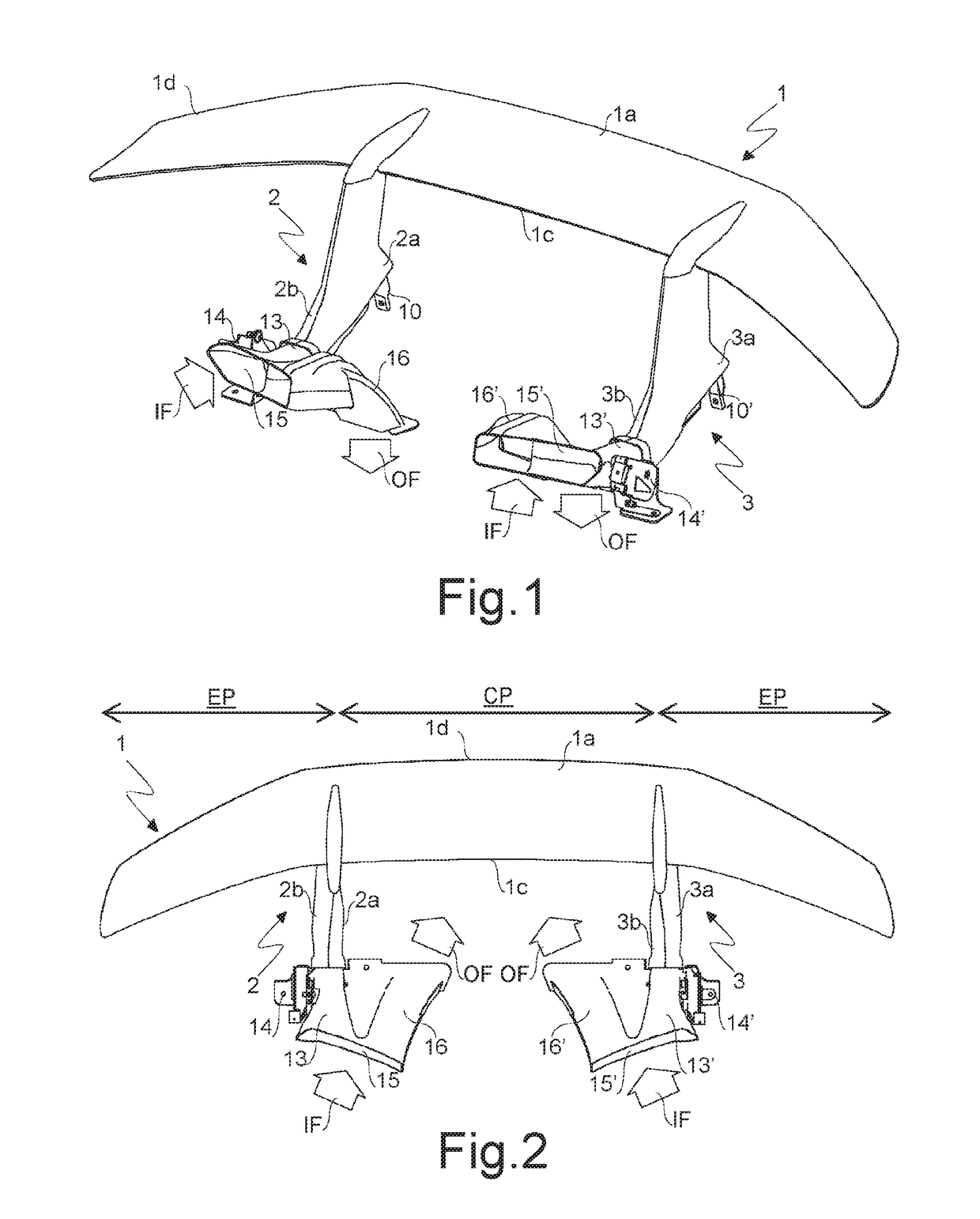
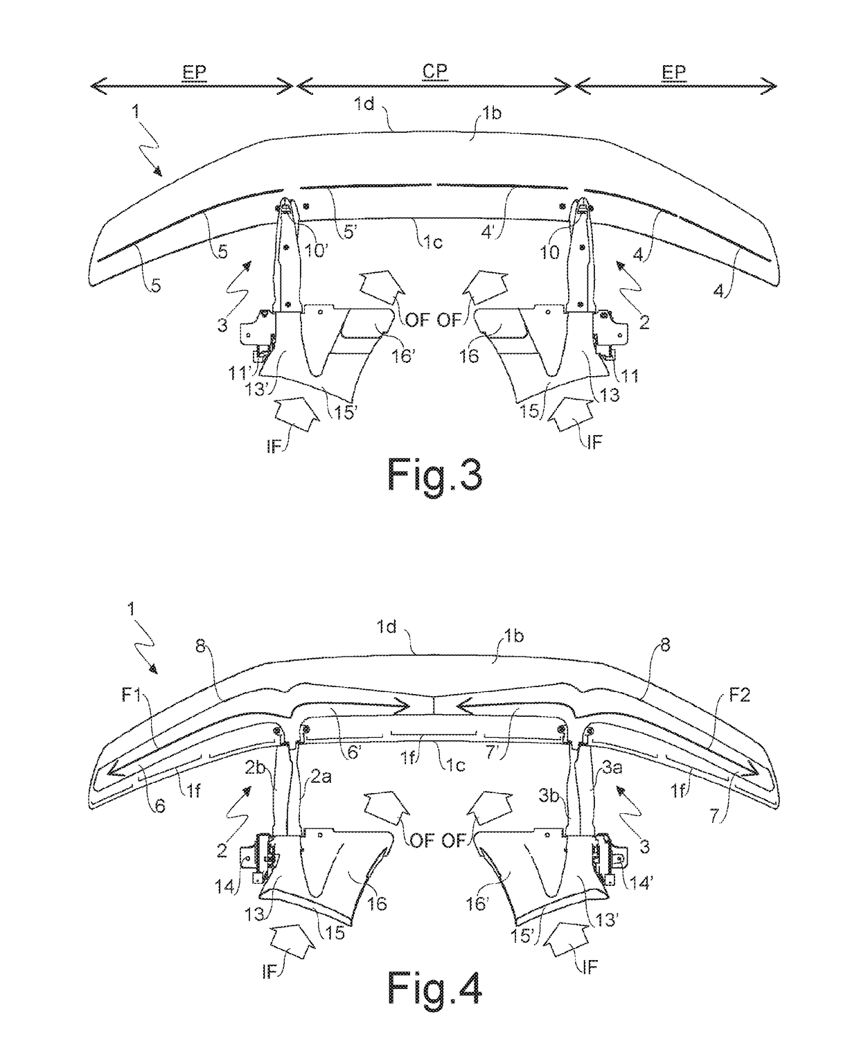
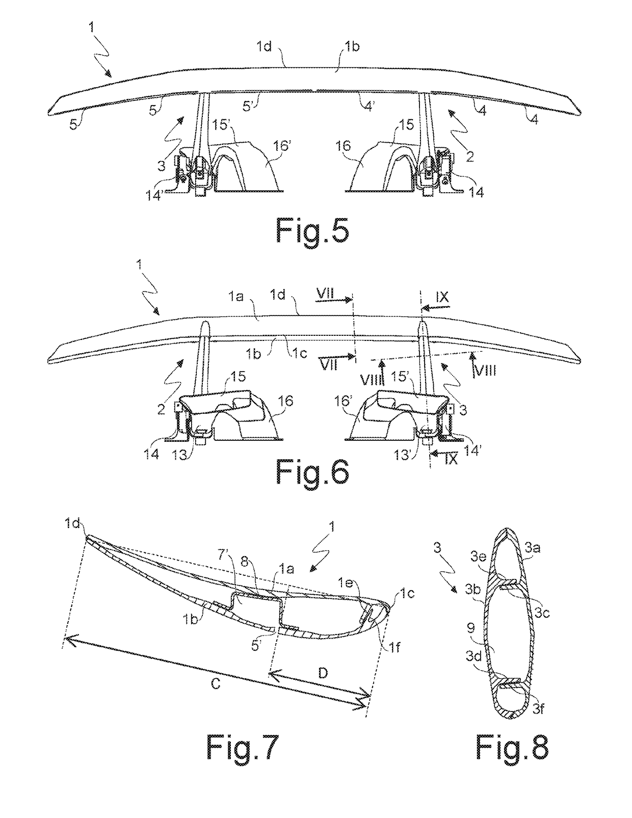
[0023]Referring to FIGS. 1 to 7, it is seen that the wing 1 according to the present invention comprises an upper surface 1a predominantly concave upwards and a lower surface 1b predominantly convex downwards so as to generate a downward thrust if the wing 1 is moved forwards, in particular if it mounted on a vehicle (not shown in the figures), for example of a sports car, in motion. The wing 1 is provided with one or more supports, preferably at least two supports 2, 3, to fix the wing 1 to said vehicle, in particular on its rear portion. The supports 2, 3 may protrude below the lower surface 1b of the wing and preferably have a shape similar to a fin of an airplane. The front edge 1c of the wing 1 is concave forwards and / or the rear edge 1d of the wing 1 is convex rearwards. The wing 1 has preferably a central portion CP comprised between the supports 2, 3 and between two outer portions EP having a width between 60% and 90%, in particular between 70% and 80%, of the width of the c...


PUM


Abstract

Wing including an upper surface predominantly concave upwards and a lower surface predominantly convex downwards, which wing is provided with one or more supports to be fixed to a vehicle, in which the lower surface of the wing is provided with one or more slits that connect with the outside one or more first ducts arranged in the wing, which are in turn connected to at least one second duct arranged in at least one support, wherein at least one valve connected to at least one actuator is arranged along the second duct or along a third duct connected to this second duct. The present invention also relates to a process for controlling the operation of the wing and a motor vehicle comprising this wing.

Description

TECHNICAL FIELD[0001]The present invention relates to a wing for vehicles and in particular a wing which can be mounted on a motor vehicle to generate a downward thrust and to increase its adherence to the ground. The present invention also relates to a process for controlling the operation of the wing and a motor vehicle comprising this wing.BACKGROUND OF THE INVENTION[0002]The lower surface of a known wing for vehicles, used especially in sports cars, in particular for Formula 1 competitions, is provided with one or more slits which connect ducts arranged in the wing with the outside. The ducts in the wing are connected to an external duct which is arranged in front of the wing and is connected in turn to an air intake arranged in front of the driving seat of the motor vehicle. In this way the pilot, by manually closing the air flow that passes through said external duct, can let air pass through the slits to reduce the aerodynamic drag of the wing and its downward thrust.[0003]Sa...

Claims


Application Information

Patent Timeline
IPC IPC(8): B62D35/00
CPCB62D35/00B60K11/08B62D35/02Y02T10/88Y02T10/82
Inventor AGUGGIARO, ANDREADINI, EMILIANOPARISI, RICCARDOTORLUCCIO, ANTONIO
Owner AUTOMOBILI LAMBORGHINI
Why Eureka
Try Eureka