Cable covered in solid lubricant

a technology of solid lubricant and cable, which is applied in the direction of cable laying apparatus, manufacturing tools, insulation conductors/cables, etc., can solve the problems of non-negligible space for additional equipment, major alteration of manufacturing lines, and inability to properly control the thickness of the sheath

Inactive Publication Date: 2000-11-14
ALCATEL LUCENT SAS
View PDF5 Cites 78 Cited by
  • Summary
  • Abstract
  • Description
  • Claims
  • Application Information

AI Technical Summary

Problems solved by technology

That gives rise to a major alteration of the manufacturing line.
In addition, the equipment for depositing the lubricant must be very close to the sheath extrusion head since otherwise it is not possible to control the thickness of the sheath properly.
In any event, the additional equipment occupies non-negligible space and such an organization is not favorable for good control over the dimensions of the sheath.

Method used


Image

  • Cable covered in solid lubricant

Examples


Embodiment Construction

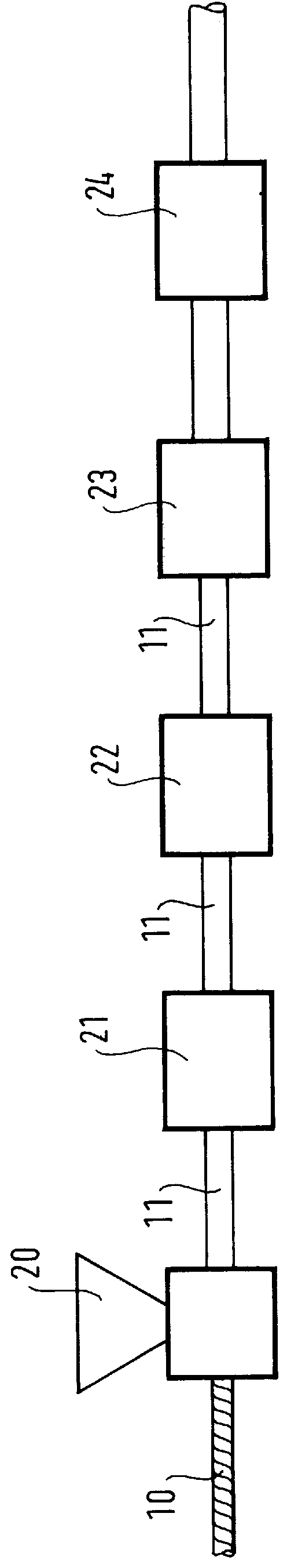
With reference to the FIGURE, and as in the prior art, an extruder 20 forms the sheath of the cable 11 on a core 10. By way of example, the core of an optical fiber cable is often constituted by a central carrier or strength member, with the fibers being received in helical grooves formed in the periphery of the strength member.

The cable 11 is then cooled in a cooling vessel 21. As mentioned above, it is necessary for the extruder 20 to be very close to the cooling vessel 21 in order to control the thickness of the sheath.

According to the invention, the cable is then directed to a preparatory treatment member 22 for preparing the sheath to receive a deposit.

The member 22 may be a heater member such as an oven or a flame, nevertheless it is necessary to avoid heating the sheath up to its melting point. The temperature of the oven is selected in a manner that is appropriate for the remainder of the method.

This member 22 may also perform treatment by the corona effect, i.e. it may subj...


PUM

PropertyMeasurementUnit
coefficient of frictionaaaaaaaaaa
thicknessaaaaaaaaaa
dimensionsaaaaaaaaaa

Abstract

The invention relates to apparatus for depositing a lubricant coating on a cable, the cable including a sheath made by means of an extruder followed by a cooling vessel. Downstream from the cooling vessel, the apparatus includes a heater member followed by a deposition chamber for depositing a lubricant material.

Description

The present invention relates to a cable covered in solid lubricant, with such a cable being designed for installation in a tubular cable duct or conduit.In numerous fields of application, and in particular telecommunications, electric or fiber optic cables are inserted into ducts. There is therefore a need to minimize the coefficient of friction between cables and the inside walls of ducts.A first known solution appears in French patent FR 2 674 364. In that document, the core of the cable passes via a first extruder which applies a conventional sheath thereto, often made of polyethylene. The sheathed core then passes through a second extruder which applies a composite lubricant layer thereto, such as an alloy of silicone resin and polyethylene. The cable lubricated in that way then passes in conventional manner through a cooling vessel.A second known solution appears in German patent application DE-44 10 456. As in the first document, that document provides for an extruder to cove...

Claims


Application Information

Patent Timeline
Patent Type & Authority Patents(United States)
IPC IPC(8): H01B13/14H01B13/06G02B6/44B29C47/02C08L27/18G02B6/46H01B13/00H02G1/08
CPCH01B13/145
Inventor BONICEL, JEAN-PIERRETATAT, OLIVIER
Owner ALCATEL LUCENT SAS
Why Eureka
Try Eureka