Surface-acoustic-wave device

a surface acoustic wave and waveguide technology, applied in piezoelectric/electrostrictive/magnetostrictive devices, semiconductor devices, piezoelectric/electrostriction/magnetostriction machines, etc., can solve the problems of increasing the volume of the saw device for mounting the saw element, giving rise to a high cost nor enlarging the volume of the saw devi

Inactive Publication Date: 2000-11-21
NEC CORP
View PDF15 Cites 59 Cited by
  • Summary
  • Abstract
  • Description
  • Claims
  • Application Information

AI Technical Summary

Problems solved by technology

A problem has been that this requirement of the electric-shield chamber entails high cost for the SAW device.
Another problem has been that provision of the electric-shield chamber causes to increase the volume of the SAW device for mounting the SAW element.
This mounting method includes a problem concerning the way of preventing an erosion of an Al pattern formed on a surface of a SAW element (the pattern of the interdigital electrodes).
The method includes another problem to be taken into account concerning the way of electric-shielding of the SAW element against an external electric field neither giving rise to a high cost nor enlarging the volume of the SAW device.
Concerning the latter problem, however, no effective method has been currently found.

Method used


Image

  • Surface-acoustic-wave device
  • Surface-acoustic-wave device
  • Surface-acoustic-wave device

Examples


first embodiment

The first embodiment described above is summarized as follows:

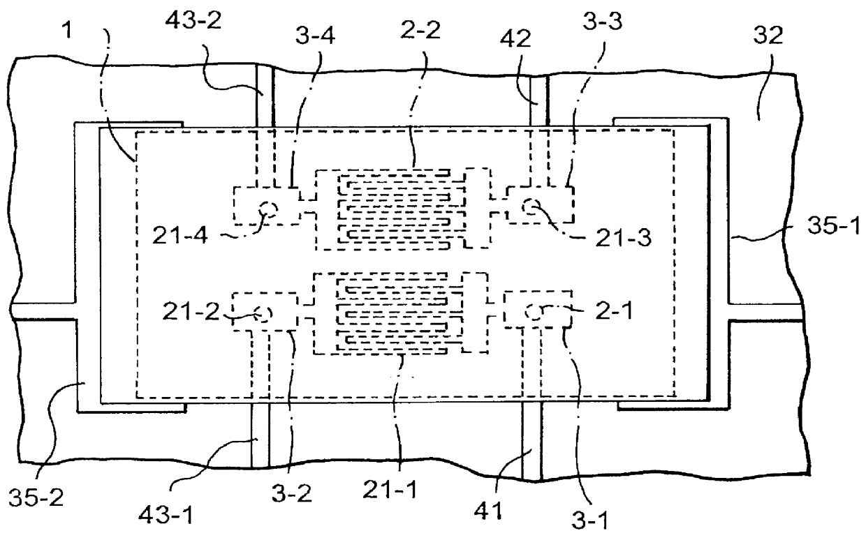
Since conductive film 32 grounded electrically through ground electrode 35 covers SAW element 1, the present embodiment can offer a SAW device shielded against an external noise field;

Since conductive film 32 is crimped (pressure-connected) and fixed to mounting substrate 36 covering SAW element 1, the strength of combination between conductive film 32 and mounting substrate 36 increases; and

Since conductive film 32 can serve as a kind of a protective wall against an external impact, the present embodiment allows relieving an external impact force acting on the SAW device.

Next, referring to FIG. 5 through FIG. 7, other embodiments will be set forth. In FIGS. 5-7, the same parts as those in FIGS. 3 and 4 are labeled with same reference numbers as denoted in FIGS. 3 and 4.

In the SAW device shown in FIG. 5 (hereinafter, referred to as a second embodiment), conductive resin member 51 is used to combine conductive film 32 with...

fourth embodiment

FIG. 7 is a cross-sectional view of the present invention.

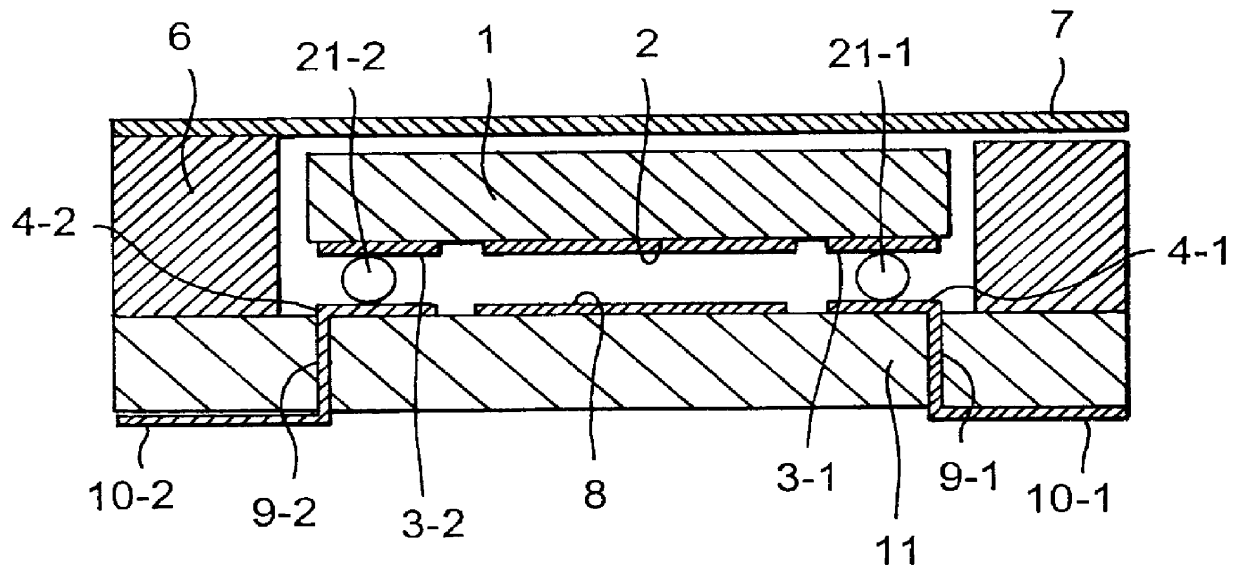
In this embodiment, multiple-layer print substrate 61 is employed. The first layer of the substrate 61 has a through-hole in which SAW element 1 is received. As a result, the first layer of multiple-layer substrate 61 surrounds SAW element 1. A second surface of SAW element 1, which is opposite to the first surface provided with interdigital electrode 2, is substantially flush with the surface of the substrate 61 on which ground electrodes 35 are formed (the surface of the first layer of the substrate 61).

Conductive film 32 is formed so as to cover both the entirety of the second surface of SAW element 1 and at least a part of ground electrode 35 formed on the surface of the first layer of the substrate 61. In this way, SAW element 1 is shut off electrically and airtightly from ambience.

Explanation concerning other constituent elements of the device and the operation thereof will be omitted for simplicity, because they are si...


PUM


Abstract

The surface-acoustic-wave device has surface-acoustic-wave element 1 provided with interdigital electrodes 2, shut-off member 32 and ground patterns 35-1, 35-2. Interdigital electrodes 2 are formed on a first surface of surface-acoustic-wave element 1 and covered with protective film 33. Surface-acoustic-wave element 1 is mechanically supported above mounting substrate 36. Shut-off member 32 serves to shut off surface-acoustic-wave element 1 electrically and airtightly from an ambience. The ground patterns 35-1, 35-2, grounded electrically, serve to discharge an electric charge. Ground patterns 35-1, 35-2 contact a surface of mounting substrate 36. Shut-off member 32 covers surface-acoustic-wave element 1 and also is connected with ground patterns 35-1, 35-2 that are in contact with the surface of mounting substrate 36.

Description

1. Field of the InventionThe present invention relates to a surface-acoustic-wave device (hereinafter, referred to as a SAW device). In particular, the present invention relates to a SAW device having a SAW element on which interdigital electrodes are formed and which is covered with a conductive thin-film to shield the SAW element against an external electric field.2. Description of the Related ArtFIG. 1 represents an example of construction of a SAW device currently in use.Interdigital electrodes 2 and I / O (input / output) electrodes 3-1, 3-2 are formed of aluminum (Al) thin films on one surface of a SAW element 1. SAW element 1 is formed on ceramic substrate 11 with interposition of ground pattern 8. I / O terminals 10-1 and 10-2 are formed on ceramic substrate 11.I / O electrode 4-1 is connected with I / O terminal 10-1 via through-hole 9-1. Similarly, I / O electrode 4-2 is connected with I / O terminal 10-2 via through-hole 9-2.I / O electrodes 3-1, 3-2 formed on the surface of SAW element ...

Claims


Application Information

Patent Timeline
Patent Type & Authority Patents(United States)
IPC IPC(8): H03H9/05H03H9/25
CPCH03H9/059H03H9/1078H03H9/1071H01L2224/16225H01L2924/16195
Inventor FUKIHARU, EIICHI
Owner NEC CORP
Why Eureka
Try Eureka