Bracket for bathtubs

a bathtub and bracket technology, applied in the field of bathtub brackets, can solve the problems of cumbersome assembly of the relationship between the different parts of the brack

Inactive Publication Date: 2000-12-05
ROYAL BANK OF CANADA AS COLLATERAL AGENT +1
View PDF7 Cites 2 Cited by
  • Summary
  • Abstract
  • Description
  • Claims
  • Application Information

AI Technical Summary

Benefits of technology

FIGS. 3 and 4 are enlarged cross-sectional views of the area IV in FIG. 1, sequentially showing the bracket in released and attached positions, respectively, with FIG. 4 moreover suggesting in phantom lines an alternate deformed condition of the resilient body of the bracket, suggesting that this body can self-compensate for dimensional differences of the fixed casing resulting from construction plays.

Problems solved by technology

The disadvantage of the Benjamin attachment method is that it is complex in that the relationship between the different parts of the bracket are cumbersome to assemble.

Method used


Image

  • Bracket for bathtubs
  • Bracket for bathtubs
  • Bracket for bathtubs

Examples


Embodiment Construction

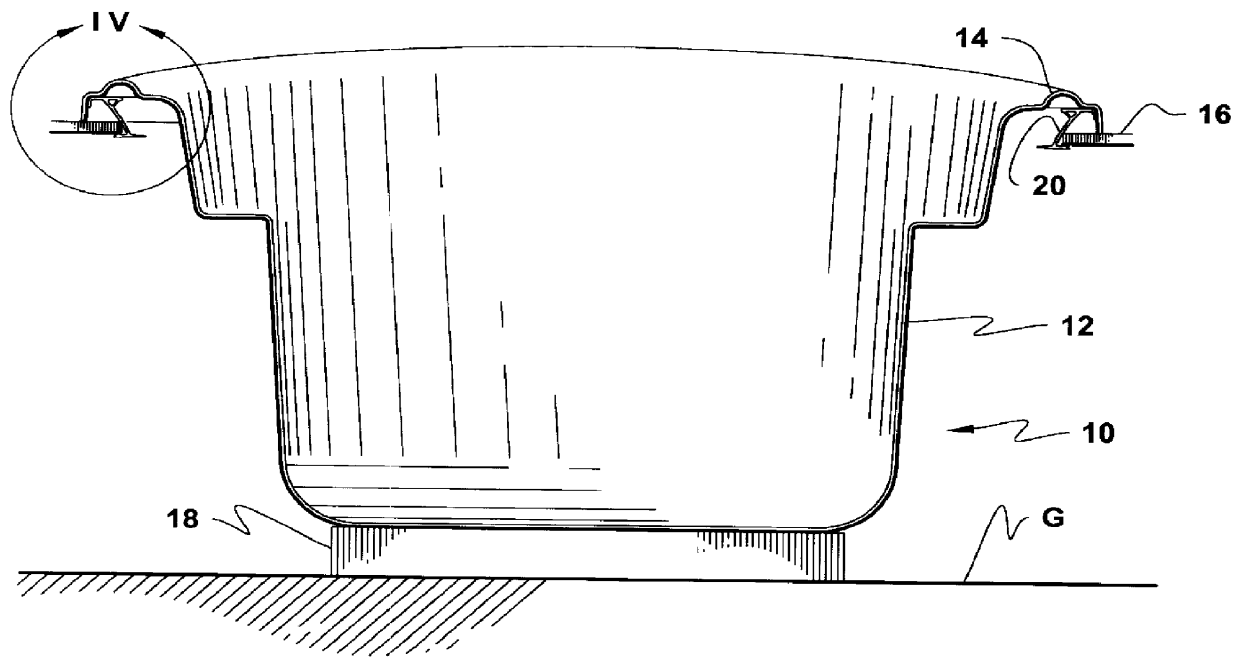
FIG. 1 shows a bathtub 10 of conventional configuration, i.e. having a main hollow body 12 to be filled with water. Body 12 is provided with a flooring and an integral peripheral upwardly outwardly inclined wall with a top, outturned, downwardly depending peripheral rim 14 which has an inner concave underface. Rim 14 transversely rests adjacent and over a fixed casing peripheral flat edge portion 16. The casing (not shown) may be of various types, for example a self-standing podium-type casing which rests on the ground, or a number of fixed panels which, in combination with the walls of the room in which the tub is installed, form a fixed skirt around the tub 10. In any event, the casing is provided with an inner opening in which the tub is to be inserted, and defines a fixed casing inner peripheral edge portion 16. The casing can be characterized as an anchor element having a flat horizontal raised wall having top and bottom flat wall surfaces and a free edge portion, as shown in t...


PUM


Abstract

The bracket is to be installed to the inner face of the peripheral rim of a bathtub, to attach the latter to the inner peripheral edge portion of a fixed casing. The bracket has a rigid head portion which is fixedly attached to the inner rim of the bathtub, and a downwardly depending arcuate resilient foot which carries at its lower end a foot. When installing the bathtub inside the casing and more particularly inside the casing peripheral edge portion, the tub is downwardly displaced until its rim comes into downward abutment against the casing peripheral edge portion, the bracket slidingly abutting against the casing peripheral edge portion with a corresponding resilient foot deformation, allowing the foot to slide under the casing peripheral edge portion and to snap itself thereunder for preventing vertical displacement of the bathtub relative to the casing peripheral edge portion. Indeed, the casing peripheral edge portion is then wedged between the bracket foot and the bathtub rim.

Description

The present invention relates to brackets for installing a bathtub to a fixed casing.U.S. Pat. No. 4,290,154 issued in 1981 to W. H. Benjamin shows at FIG. 6 of this patent, a bracket used to fixedly attach the bathtub to a fixed structure, e.g. a wall. The bracket comprises two distinct parts, an apron retaining member and a holding strip. The apron retaining member is fixedly attached to the inner face of the bathtub skirt, and is elbowed so as to be spaced therefrom. The holding strip is nailed to the wall, and comprises an upper rib and a lower upwardly extending finger which forms a channel. The bathtub skirt is to be downwardly inserted inside the channel formed by the holding strip finger, while this same finger is to upwardly engage the space located between the apron retaining member and the bathtub skirt inner face. Thus, the bathtub is fixedly attached to the wall.The disadvantage of the Benjamin attachment method is that it is complex in that the relationship between the...

Claims


Application Information

Patent Timeline
Patent Type & Authority Patents(United States)
IPC IPC(8): A47K3/16A47K3/02
CPCA47K3/16A47K3/02
Inventor DONNELLY, STEVE
Owner ROYAL BANK OF CANADA AS COLLATERAL AGENT
Why Eureka
Try Eureka