
Weld bead chopper

a technology of chopper and bead, which is applied in the field of welding bead, can solve the problems of operator injury, strip clogging, and operator laceration and/or burns, and requires a lot of skill

Inactive Publication Date: 2000-12-12
EMPIRE PRECISION TOOLING
View PDF8 Cites 14 Cited by
  • Summary
  • Abstract
  • Description
  • Claims
  • Application Information

AI Technical Summary

Problems solved by technology

This requires much skill, partly because the hot, sharp strip has a tendency to curl unpredictably.
As a result, it is not unusual for accidents to occur and the operator to be lacerated and / or burned.
However, this method, and others like it, still require manual feeding of an end of the strip in order to start the disposal process.
Notwithstanding the apparent appeal of this chopping device, it is not being used commercially.
It is believed that one of the reasons is the ease with which the slotted guide in the apparatus can become jammed, particularly by light gauge scarfed weld bead, because of the unpredictable spiral curliness of the bead as it leaves the scarfing tool.
Another disadvantage of Omura apparatus is that the cut chips of weld bead are expelled from the cutter in the direction of the scarfed tube.
Since the weld beads are hard, they can cause damage to the tube and to any rolls, e.g. ironing rolls that are located in the vicinity of the chopping device.

Method used


Image

  • Weld bead chopper
  • Weld bead chopper
  • Weld bead chopper

Examples


Embodiment Construction

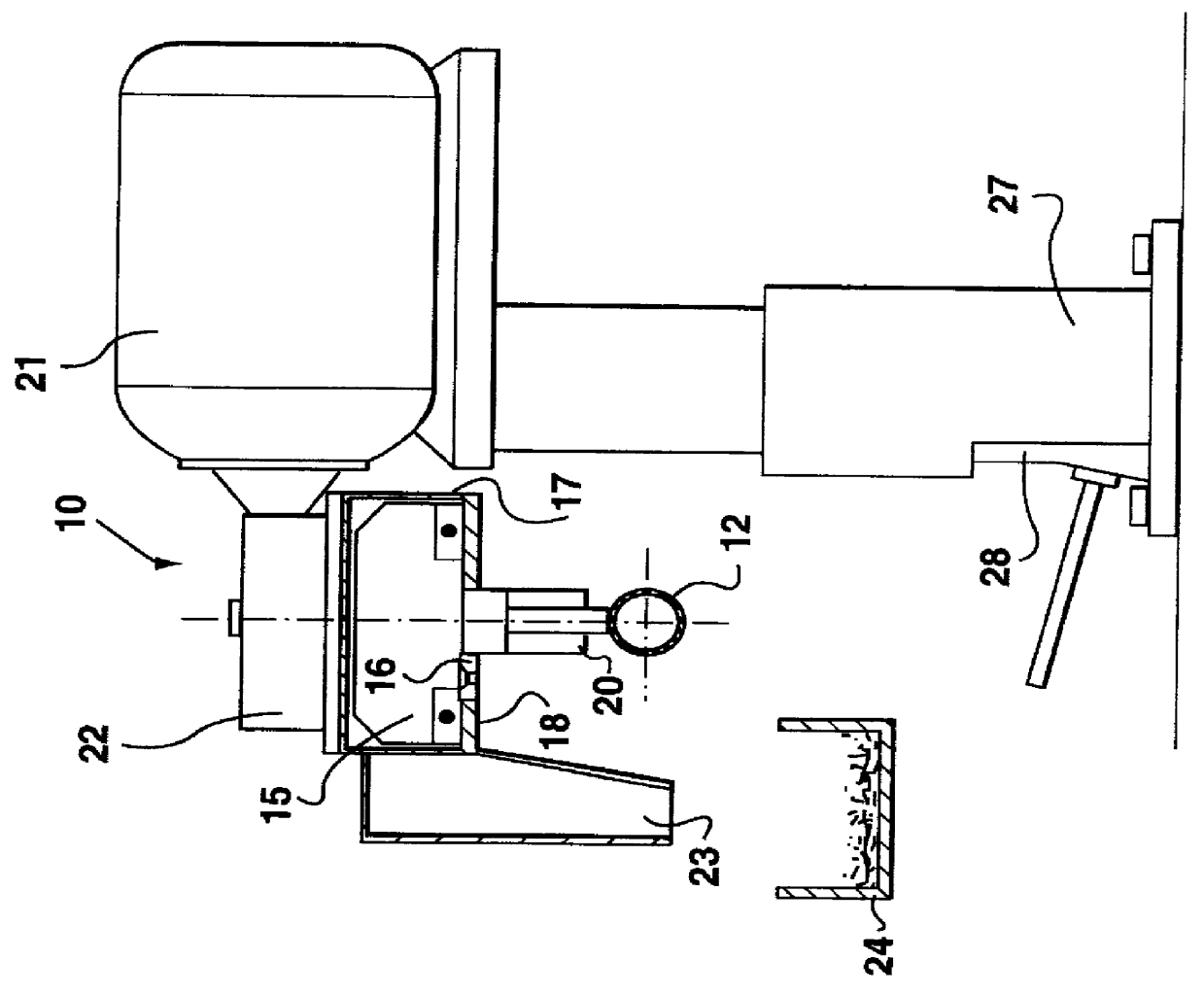
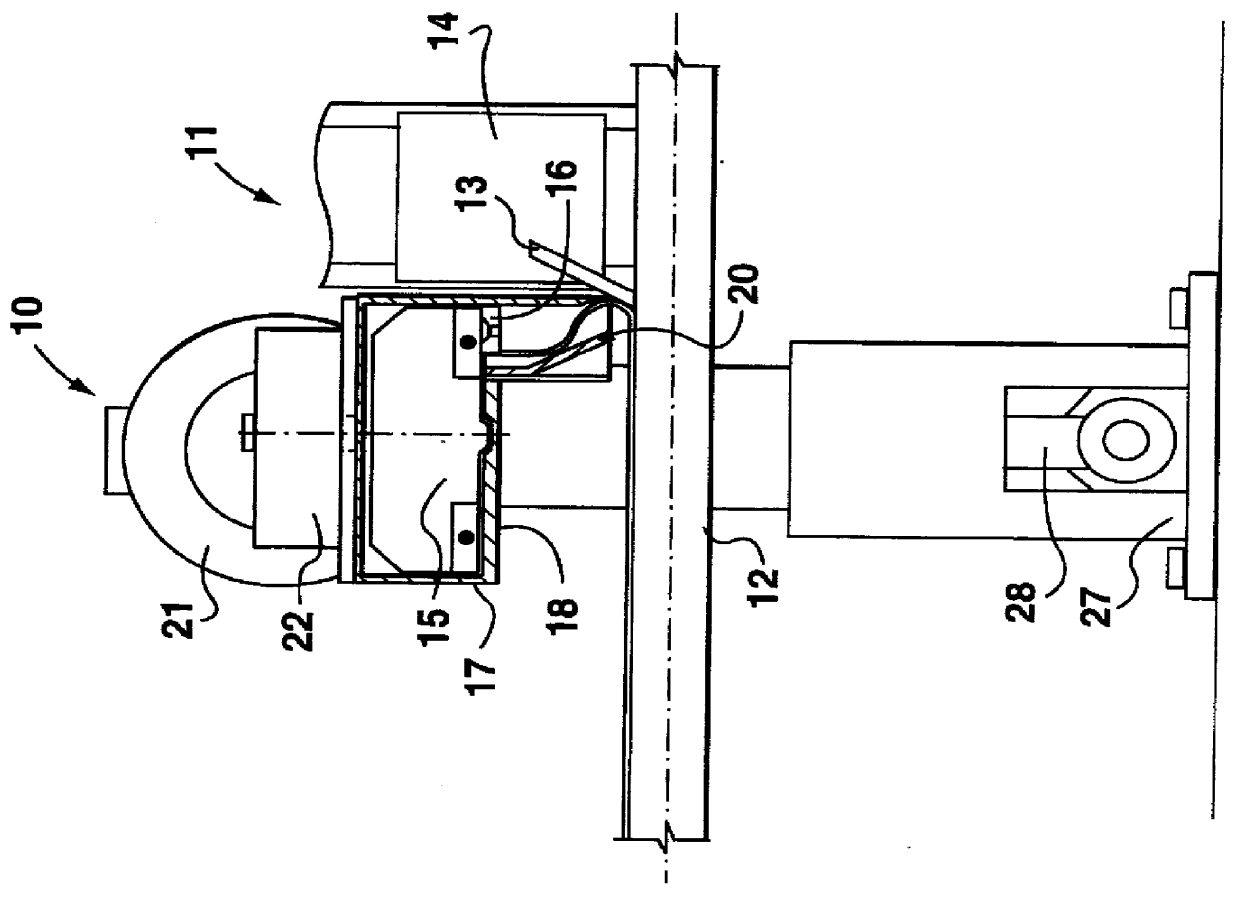
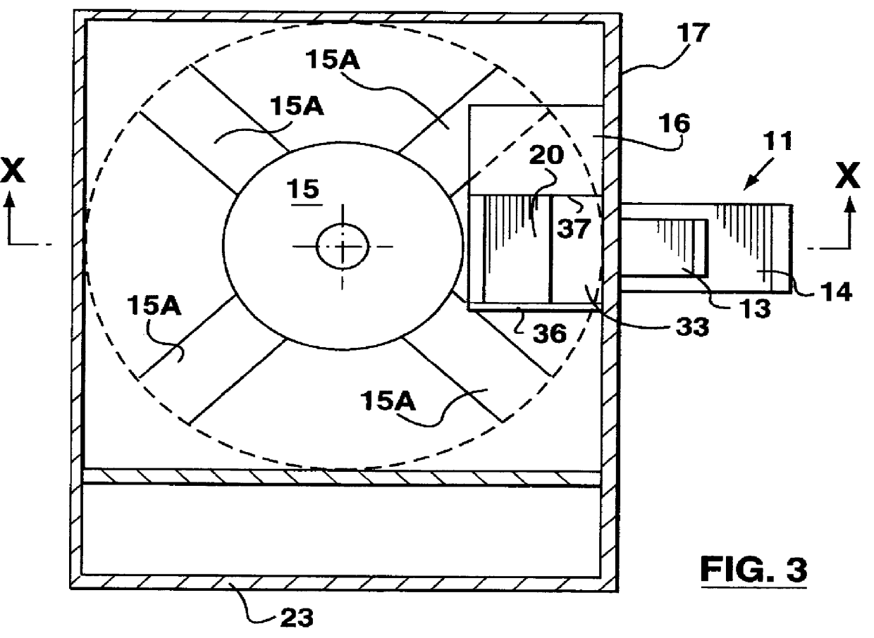
A chopping apparatus was constructed similar to that shown in FIGS. 1 to 4. The rotary cutter was about 12.5 cm in diameter by 10 cm high with square shaped blades about 4.8 cm thick. The cutter was driven by a 2 horsepower motor with a 1:5 gear reducer. The cutting head rotated at about 350 rpm. The distance between the tube to the chopping surfaces was about 48 mm. The throat was 19 mm by 38 mm mouth opening and about 35 mm high.

A tube of 12.7 cm diameter with wall thickness of 3.8 mm was longitudinally welded at a rate of 38 meters of tube per minute. The weld bead was thus scarfed at the same rate. The chopping apparatus produced weld bead chips of about 28 mm long, which were deposited in a collection box below the tube. The chopping apparatus was in continuous operation for about 16 hours without interruption and without jamming. This compares with manual methods of operation where scarfed bead coils must be disposed of every 20 to 25 minutes and the weld bead must be re-wound...


PUM

PropertyMeasurementUnit
distanceaaaaaaaaaa
distanceaaaaaaaaaa
distanceaaaaaaaaaa

Abstract

A weld bead chopper is provided, for use in combination with a scarfing tool which is intended to scarf a longitudinal weld bead from a tube. The chopper has a) a chopper blade which is rotatable about an axis which is substantially perpendicular to a longitudinal axis of the tube, and b) a stationary blade which is cooperable with the rotatable blade. The cooperating chopping surfaces of the rotatable and stationary blades are at a short distance from the weld bead, e.g. less than 100 mm, and preferably from 20 to 50 mm. The scarfed weld bead enters an enclosed throat which has walls to guide a scarfed weld bead towards the cooperating chopping surfaces. The throat has a first guide adjacent to the scarfing tool which directs the scarfed weld bead towards a second guide. The second guide faces the scarfing tool, and is adapted to guide the scarfed weld bead towards the cooperating chopping surfaces. The throat has a cross-sectional area substantially larger than the cross-sectional area of the scarfed weld bead. Additionally, the throat has a mouth which is sufficiently small to prevent the scarfed weld bead from exiting from the mouth.

Description

The present invention relates to a chopper for chopping a weld bead. In particular it relates to a chopper for chopping weld beads which have been scarfed from the external surface of a longitudinally welded tube.BACKGROUND TO THE INVENTIONIt is known to use a scarfing tool to remove excess weld material from a longitudinally welded metal tube. The scarfed weld material comes off in a strip, which is very hot and, in places, razor sharp. Methods have been used to collect the strip and at the same time to prevent the strip from flailing about. Typically, the hot strip is wound onto a spool on a winder, as disclosed for example in U.S. Pat. No. 5,368,218, which issued Nov. 29, 1994 to Kazuo Omura. When the spool is full, the strip accumulation process must be stopped, and the strip must be cut so that the now-heavy full spool, or the wound strip, can be removed from the winder. To restart the strip accumulation process, a newly formed strip must be fed onto the winder. At start up of ...

Claims


Application Information

Patent Timeline
Patent Type & Authority Patents(United States)
IPC IPC(8): B21C37/08
CPCB21C37/0811
Inventor CALVO, SR., JULIOASENSIO, JOSE
Owner EMPIRE PRECISION TOOLING
Learn More