Hydrofoil supported water craft

a technology of hydrofoil and watercraft, which is applied in the direction of special-purpose vessels, vessel construction, transportation and packaging, etc., can solve the problems of introducing a relatively large additional resistance component, affecting the operation of the vessel, and a relative large "hump" resistance, so as to reduce the hump resistance of the craft, reduce the wake generation, and reduce the effect of high speed resistan

Inactive Publication Date: 2000-12-26
STELLENBOSCH UNIVERSITY
View PDF21 Cites 44 Cited by
  • Summary
  • Abstract
  • Description
  • Claims
  • Application Information

AI Technical Summary

Benefits of technology

It is accordingly an object of the present invention to provide a novel hydrofoil arrangement for a water craft which will have advantages over the known arrangements, identified above at least under certain conditions. Thus one object of the present invention is to provide a hydrofoil arrangement which it is believed will reduce hump resistance of the

Problems solved by technology

Prior to reaching design speed, both the demi-hulls and the hydrofoils exert a relatively large drag force on the craft, and consequently a relatively large "hump" resistance is encountered.
However, by raising the bow of the hull, the angle of attack of the main hydrofoil is changed, affecting its operation.

Method used


Image

  • Hydrofoil supported water craft
  • Hydrofoil supported water craft
  • Hydrofoil supported water craft

Examples


Embodiment Construction

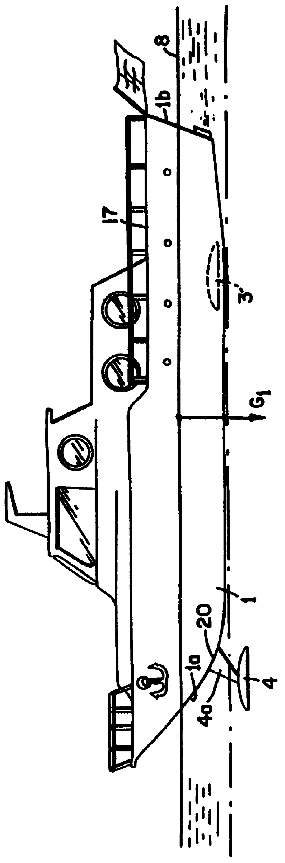
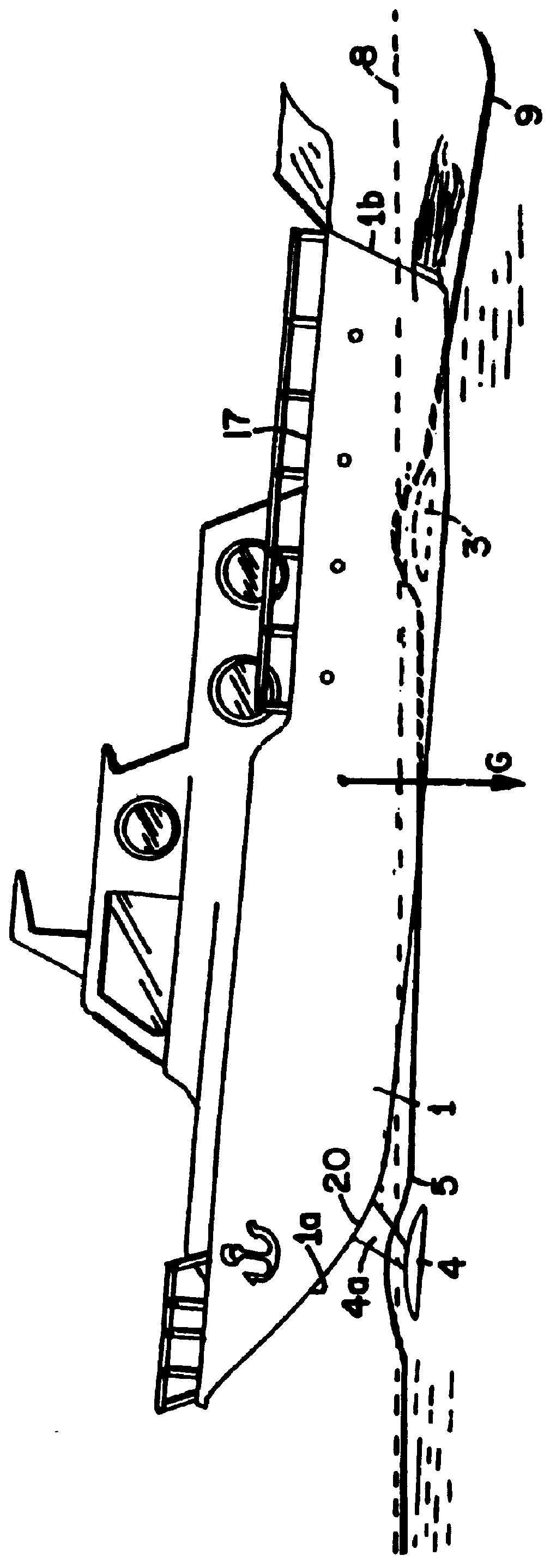
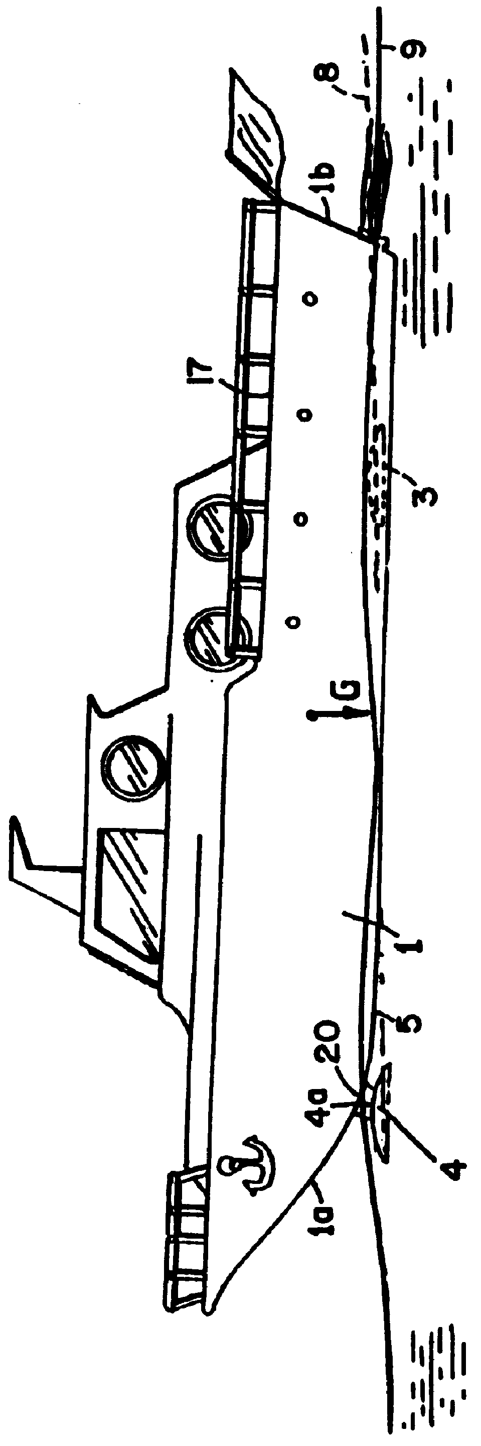
Referring to the drawings, a catamaran in accordance with the invention comprises a pair of spaced demi-hulls 1 which are coupled together in spaced relationship by means of a super structure 17 so as to define a tunnel 2 with wide walls 2a, between the demi-hulls 1 and the super structure 17 for the free passage of water flow.

A rear hydrofoil member 3 which is located between the longitudinal center of gravity (LCG) 15 of the craft and the transoms 1b of the demi-hulls 1, bridges the tunnel and is secured to each demi-hull. Preferably the hydrofoil 3 will extend from each demi-hull 1 in a plane which is substantially normal to the hull surface, in order to minimize disturbance of the flow field around each hull 1. In order to achieve such an arrangement therefore, it is envisaged that the hydrofoil 3 may curve or be angled upwardly at its ends in order to meet the hull surface at right angles, FIGS. 7, 8, 10 and 11. It has also been found desirable that any attachment, or the like,...


PUM


Abstract

The invention provides a hydrofoil equipment water craft comprising at least one hull member, terminating at a bow and a stern, a front hydrofoil member arranged in the zone of the bow of the hull, at least partially below the hull; and a rear hydrofoil member positioned to the rear of the longitudinal center of gravity (LCG) of the hull, the front hydrofoil member being at least partially offset transversely relative to the rear hydrofoil member so that the front hydrofoil or rear hydrofoil are at least partially disposed in separate longitudinal flow streams.

Description

This invention relates to a hydrofoil supported water craft, particularly but not exclusively, a catamaran-type craft.DESCRIPTION OF PRIOR ARTA hydrofoil supported catamaran is disclosed in South African Patent No. 83 / 3503 in the name of Buro Vir Meganiese Ingenieurswese van Die Universiteit Van Stellenbosch. In the arrangement disclosed, a hydrofoil member bridges the tunnel formed between two spaced demi-hulls of the craft in a position forward of the longitudinal center of gravity (hereinafter referred to as the LCG) of the craft. Two opposed hydrofoil trim tabs are positioned to the rear of the hydrofoil member and extend partially into the tunnel, one from each hull. The above arrangement is very efficient at design speed, decreasing the drag co efficient by up to 40%. Prior to reaching design speed, both the demi-hulls and the hydrofoils exert a relatively large drag force on the craft, and consequently a relatively large "hump" resistance is encountered.In South African Paten...

Claims


Application Information

Patent Timeline
IPC IPC(8): B63B1/16B63B1/12B63B1/24B63B1/00B63B1/26
CPCB63B1/12B63B1/121B63B1/26B63B1/248B63B2001/128B63B2001/123
Inventor HOPPE, KARL GUNTER WILHELM
Owner STELLENBOSCH UNIVERSITY
Why Eureka
Try Eureka