Intervertebral prosthesis

a technology of intervertebral prosthesis and hollow body, which is applied in the field of implants, can solve the problems of long-term risk of leakage proofing criteria of hollow body

Inactive Publication Date: 2000-12-26
ZIMMER GMBH
View PDF2 Cites 207 Cited by
  • Summary
  • Abstract
  • Description
  • Claims
  • Application Information

AI Technical Summary

Benefits of technology

This object is satisfied by an implant in accordance with the present invention, which comprises an elongated elastic body which is form-elastic and takes on the form of a spiral in a force free state. The cross-section of the body is preferably rectangular, and the edges can also be rounded off. It is also possible to use bodies with a roundish cross-section as long as an essentially form-fitted, tilt-proof position of the spiral is retained under load. The cross-section of the elastic body need not be constant over its entire length, but rather it turns out that its thickness can preferably decrease in the outward direction. Such a spiral has the advantage that it winds itself, does not bend when thrust in and can be severed at a suitable rolled-up length.
The implant as such can take the form of a cylindrical disc, i.e. can be made flat, or else can have inward and / or outward curvatures which follow the contours of the vertebral surfaces. In this way, the forces produced under load can be more uniformly distributed over the vertebral surfaces. The diameter of the spiral is preferably chosen such that the space within the annulus fibrosus is filled out.
In an especially preferred embodiment, the spiral has a central middle part about which the further turns wrap themselves closely. Only small intervening spaces arise, which fill up with intervertebral fluid in the implanted state where present and which do not permit a canting of the elastic body under radial forces. By means of a suitable height to width relationship a canting of the elastic body is prevented in general. The middle piece can basically have the form of a circular cylinder, but forms such as a sphere or ellipsoid have also proved useful. It is advantageous that a short, thin transition part be joined thereto via which the connection to the remaining spiral is established. This has the advantage that the spiral remains in the tightest surface--surface packing and the greatest possible area distribution is achieved while eliminating force peaks. In a simpler embodiment of the implant the central middle piece can also be dispensed with since the contribution of its area is small in comparison with the total area.
The invention relates further to an apparatus for inserting the implant, which essentially has a tube with a rectangular cross-section into which the elastic body can be drawn in, and preferably so far that the middle piece just protrudes from the distal end of the tube. The cross-section of the tube corresponds essentially to the cross-section of the elastic body. The feeding of the body can be done by hand. However, feeding means in the form of a pusher tool which can be activated, e.g. via a lever mechanism, are preferably provided, together with a corresponding cross-sectional enlargement of the tube. The pusher tool has means at its distal end, standing in operative contact with the elastic body or the stiffening, which facilitate the feeding of the body. The means can consist of a roughening of the surface, or else of tooth-like projections with preferential orientation in the distal direction. This achieves a situation in which the extensions grip into the elastic body or the stiffening on advance of the pusher tool and push the latter along with the pusher tool, whereas they slide backwards over the surface on retraction of the pusher tool. A controlled feeding of the elastic body is thereby made possible. It is of additional advantage to provide the tube at its distal end with a one-sided narrowing of its cross-section which at its narrow end is just capable of taking up the elastic body only. This has the effect that the pusher tool, when pushed forwards, is simultaneously pushed downwards, and thus the force transmitting contact between the pusher tool and the body is increased.
The implant has the advantage of being as simple as possible in its construction and of ensuring a supporting effect uniformly over a greater part of its area. The implant has the further advantage of not having to be fixed in a spiral form by additional means, but can be inserted with comparatively simple and easy to use instruments.

Problems solved by technology

Furthermore, the leak-proofing criteria of the hollow body represent a long-term risk when the great stresses in the region of the vertebral column are taken into account.
Only small intervening spaces arise, which fill up with intervertebral fluid in the implanted state where present and which do not permit a canting of the elastic body under radial forces.

Method used


Image

  • Intervertebral prosthesis
  • Intervertebral prosthesis
  • Intervertebral prosthesis

Examples


Embodiment Construction

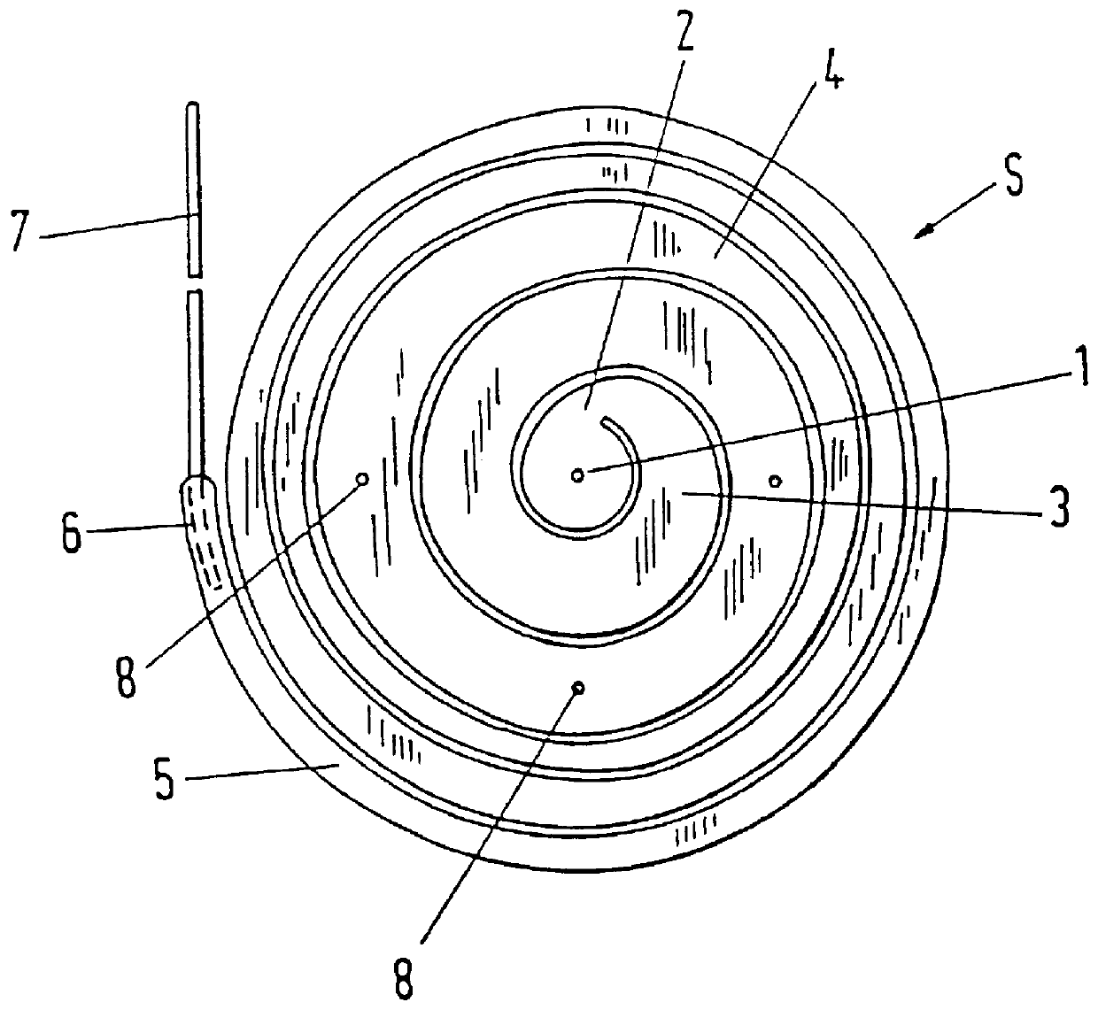
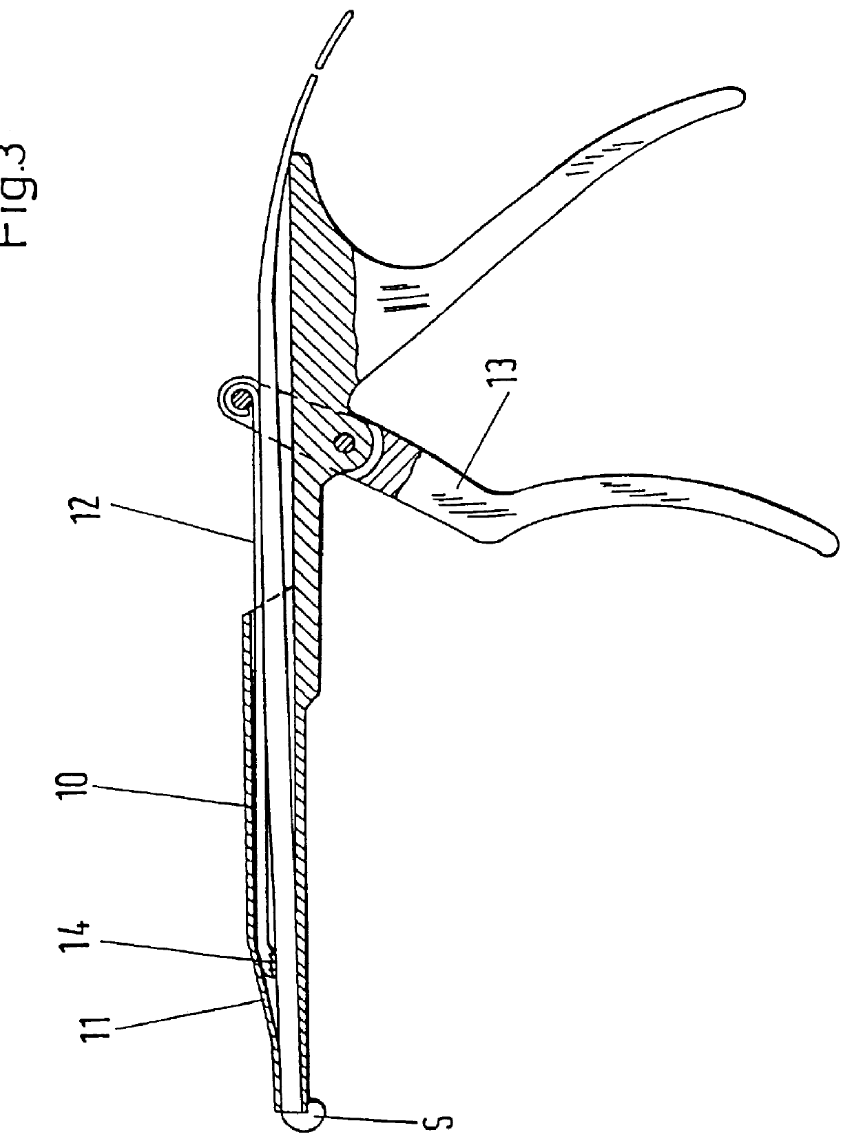
The Figures deal with an implant, in particular an intervertebral prosthesis preferably of an elongated elastic body, which is form-elastic and takes on the form of a spiral S in the force free state. The spiral can be drawn by reverse winding up into an insertion instrument, which is only insubstantially larger in the insertion region than the cross-section of the elongated elastic body in order to reach the inner space of an intervertebral disc through a small opening in the annulus fibrosus and to push in and separate off the self winding spiral when the inner space is filled. This has the advantage that inner spaces of differing sizes can be filled with the same spiral.

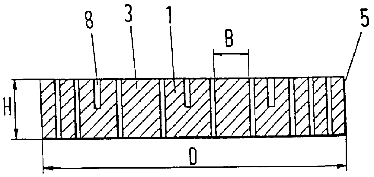
FIG. 1 shows the spiral implant with a central middle part 1, which has essentially the form of a cylinder. This is joined at the side by a thin region 2 which permits a pronounced angular deflection and thus a form-fitted transition to the spiral turn 3 connected to it, essentially without intervening spaces.

In t...


PUM


Abstract

An implant, in particular an intervertebral prosthesis, which consists of an elongated elastic body which is form-elastic and takes on the form of a spiral S in the force free state. The spiral can be drawn by a reverse winding up into an insertion instrument which is only insubstantially larger in the insertion region than the cross-section of the elongated elastic body in order to reach the inner space of an intervertebral disc through a small opening in the annulus fibrosus and to push in and sever off the self winding spiral when the interior is filled. This has the advantage that inner spaces of differing sizes can be filled with the same spiral.

Description

1. Field of the InventionThe invention relates to an implant, in particular an intervertebral prosthesis, consisting of an elongated elastic body.2. Description of the Prior ArtA prosthesis of this type is known from EP-A-0 453 393. It serves as replacement for a damaged intervertebral disc nucleus (nucleus pulposus). With this prosthesis the outer ring (annulus fibrosus) of a natural intervertebral disc remains intact for the most part. The known prosthesis consists of a fluid-tight hollow body which is filled with an incompressible flowable medium. This prosthesis requires for its implantation a specially formed insertion instrument by means of which the hollow body is intraoperatively coiled up into a spiral form and can subsequently be filled. This places high demands on the skill of the surgeon on the one hand, as well as on the manufacture of the insertion instrument with respect to the coiling mechanism, as well as with regard to the filling apparatus. Furthermore, the leak-p...

Claims


Application Information

Patent Timeline
Patent Type & Authority Patents(United States)
IPC IPC(8): A61B17/32A61F2/44A61F2/46A61F2/00A61F2/30A61B17/00A61B17/56
CPCA61B17/3201A61F2/442A61F2/4611Y10S606/91A61F2002/3008A61F2002/30225A61F2002/30293A61F2002/30573A61F2002/4415A61F2002/444A61F2002/4622A61F2002/4627A61F2002/4628A61F2230/0069A61F2230/0091A61F2250/0098A61F2310/00023Y10S606/907A61B2017/00469
Inventor HUSSON, JEAN-LOUISBAUMGARTNER, WALTERFREUDIGER, STEFAN
Owner ZIMMER GMBH
Why Eureka
Try Eureka