

Zoom lens and optical apparatus using the same
a technology applied in the field of zoom lens and optical apparatus, can solve the problems of increasing the bulk and size of the entire lens system, increasing the complexity of the structure, and the inability to adjust the zoom lens
Inactive Publication Date: 2000-12-26
CANON KK
View PDF2 Cites 82 Cited by
- Summary
- Abstract
- Description
- Claims
- Application Information
AI Technical Summary
Problems solved by technology
In the zoom lens configuration that has made the third lens unit negative in refractive power, however, because the diverging rays of light from the second lens unit are further diverged by the third lens unit, the diameter of the fourth lens unit becomes larger, causing the of increasing the bulk and size of the entire lens system.
However, because the third lens unit is movable, the mechanism therefor results in an increased complexity of structure.
However, there are disclosed no zoom lenses having a double-aspherical lens in the third lens unit.
Method used
View moreImage
Smart ImageViewing Examples

Examples
numerical example 2
______________________________________
numerical example 3
______________________________________
TABLE 1
first embodiment
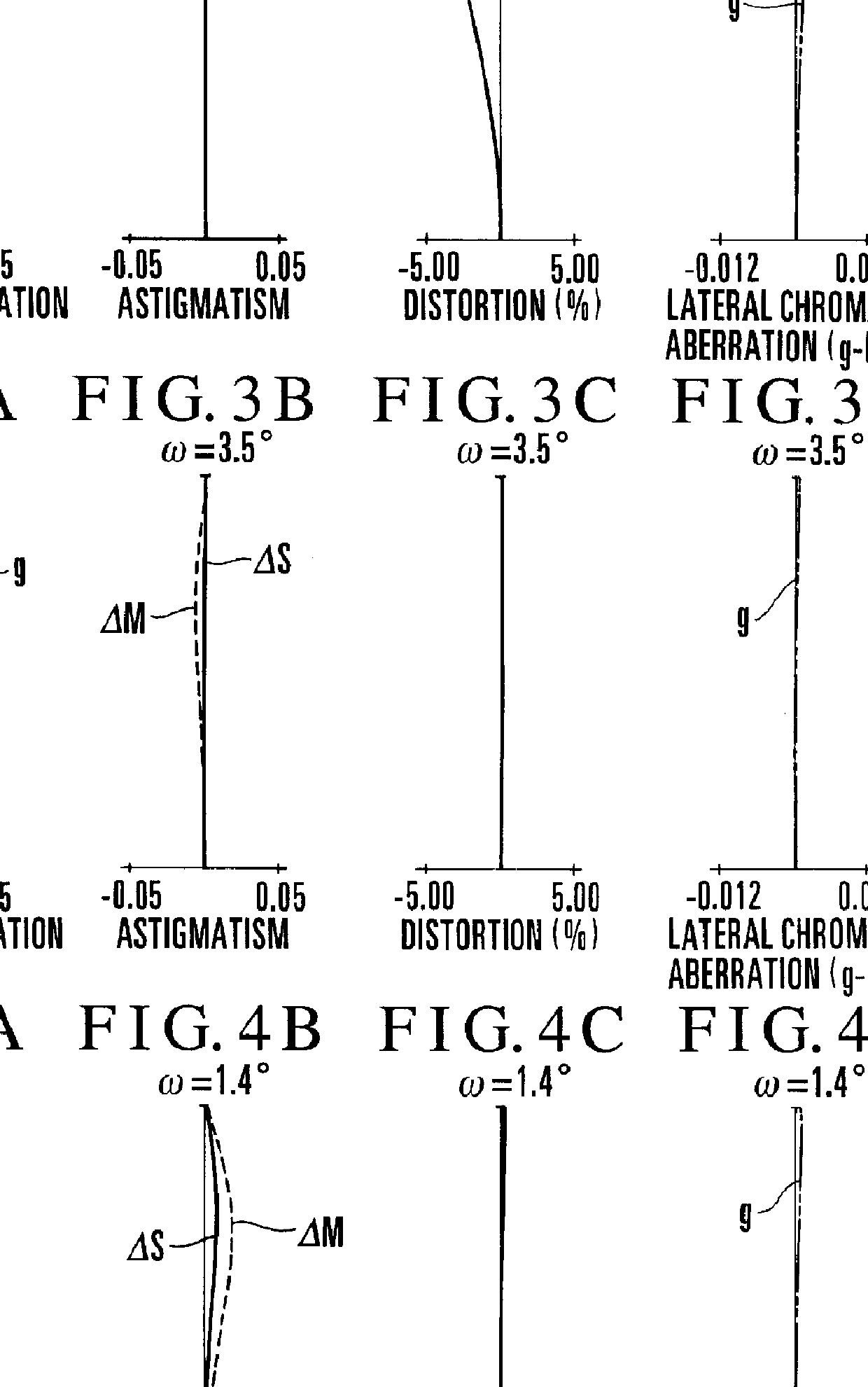
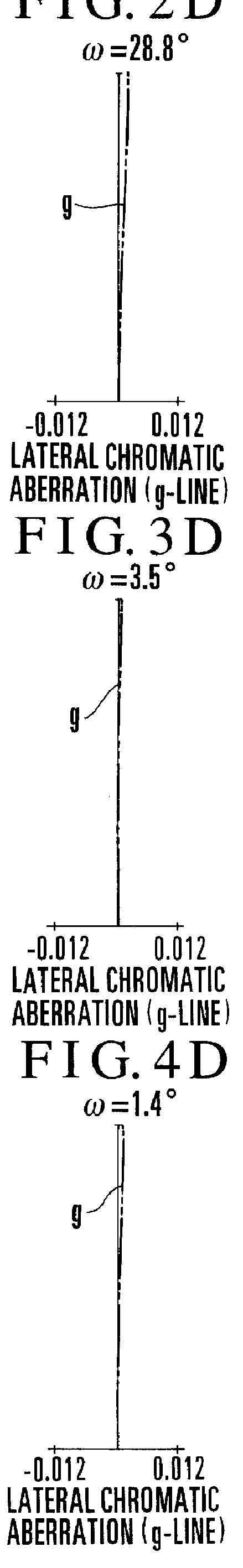
It will be appreciated from the foregoing that, the bulk and size of the entire lens system are minimized and, despite the very high zoom ratio and as fast a speed as about 1.6 in F-number, a high optical performance is obtained. Such a zoom lens is achieved by using a smaller number of constituent lenses than was heretofore usual. Further, an excellent optical apparatus using the zoom lens can be realized.
Login to View More PUM
 Abstract
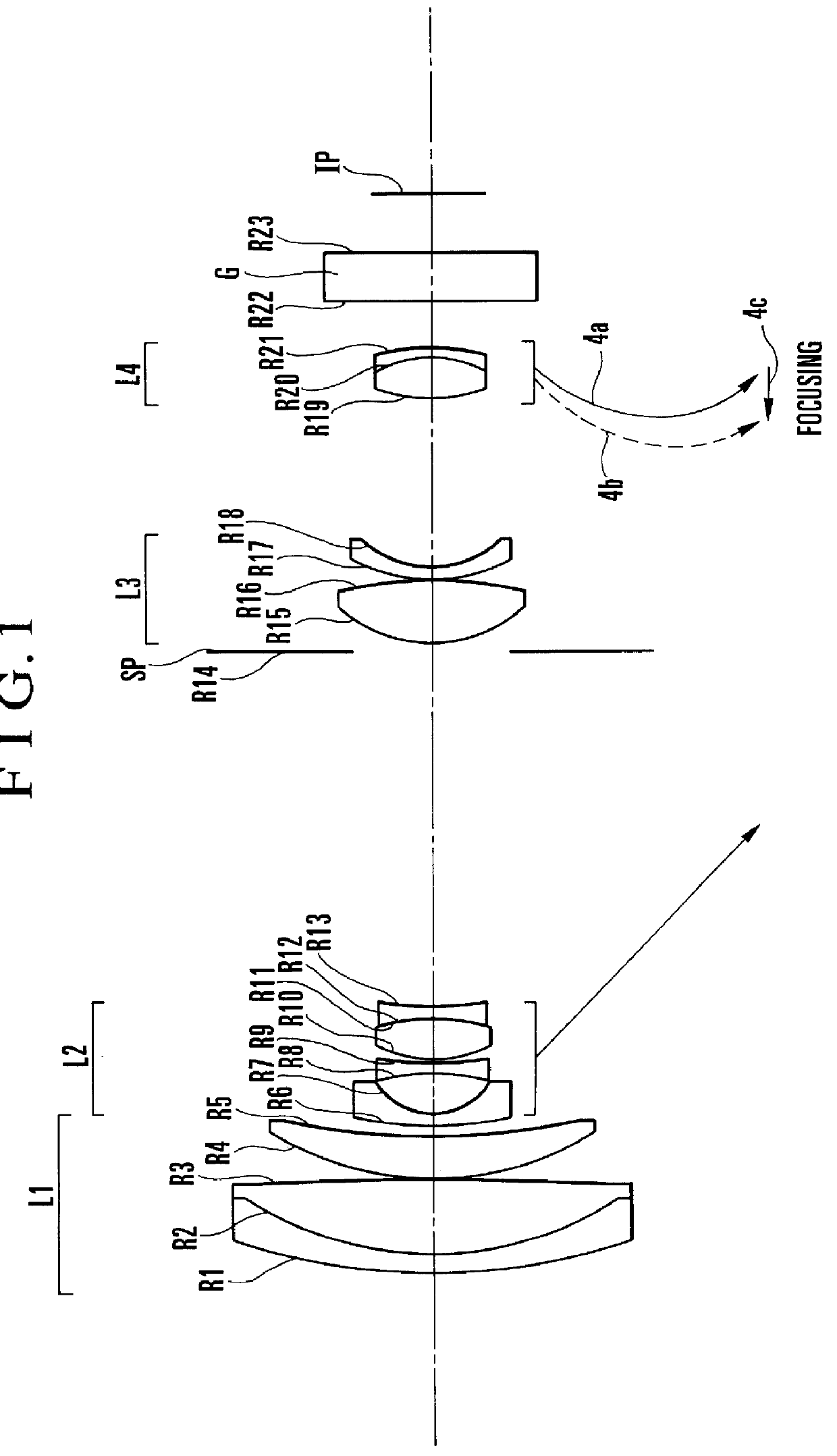
A zoom lens includes, in order from an object side to an image side, a first lens unit of positive refractive power, a second lens unit of negative refractive power, a third lens unit of positive refractive power and a fourth lens unit of positive refractive power, zooming from a wide-angle end to a telephoto end being effected by moving the second lens unit toward the image side, and shifting of an image plane due to zooming being compensated for by moving the fourth lens unit, wherein the second lens unit consists of four separate single lenses including three negative lenses and one positive lens, and the third lens unit has at least one positive lens both surfaces of which are aspherical.
Description
1. Field of the InventionThe present invention relates to a zoom lens and an optical apparatus using the same and, more particularly, to a zoom lens utilizing the rear-focus method and having a high range with a relatively small number of constituent lenses, suited to be used in video cameras, film cameras and broadcasting cameras, and an optical apparatus using the same.2. Description of Related ArtFor a zoom lens to be used in a photographic camera, a video camera or like optical apparatus, the use of a lens unit other than the front or first lens unit in focusing, or the so-called "rear-focus" method, has been previously proposed in many examples. This is because the rear-focus method admits a lens unit of relatively small size and light weight to move during focusing. Therefore, the driving torque can be weak and, nonetheless, fast focus adjustment can be effected, so that the rear-focus method has an advantage for good adaptation to the auto-focus system.Such a rear-focus type ...
Claims
Login to View More Application Information
Patent Timeline
 Patent Type & AuthorityPatents(United States)
IPC IPC(8): G02B15/163G02B15/173
CPCG02B15/173G02B15/144113
InventorHORIUCHI, AKIHISA
OwnerCANON KK