Exposure apparatus and method for producing device

a technology of producing device and exposure apparatus, which is applied in the direction of photomechanical apparatus, printing, instruments, etc., can solve the problems of insufficient margin, difficult to match the substrate surface with respect to the image plane of the projection optical system, and inability to obtain desired pattern transfer accuracy

Inactive Publication Date: 2005-10-06
NIKON CORP
View PDF53 Cites 197 Cited by
  • Summary
  • Abstract
  • Description
  • Claims
  • Application Information

AI Technical Summary

Benefits of technology

[0009] The present invention has been made taking the foregoing circumstances into consideration, an object of which is to provide an exposure apparatus and an exposure method in which a pattern can be transferred

Problems solved by technology

If the depth of focus δ is too narrowed, it is difficult to match the substrate surface with respect to the image plane of the projection optical system.
It is feared that the margin is insufficient during the exposure operation.
As a result, it is feared that any desired pattern transfer accuracy cannot be obtained.
Further, an inconvenience also arises, for example, such that any rust appears due to the outflowed fluid on mechanical parts or the like arranged around the substrate stage for supporting the substrate P. It is also conceived that the liquid is prevented from any outflow by omitting the exposure for the edge ar

Method used


Image

  • Exposure apparatus and method for producing device
  • Exposure apparatus and method for producing device
  • Exposure apparatus and method for producing device

Examples


first embodiment

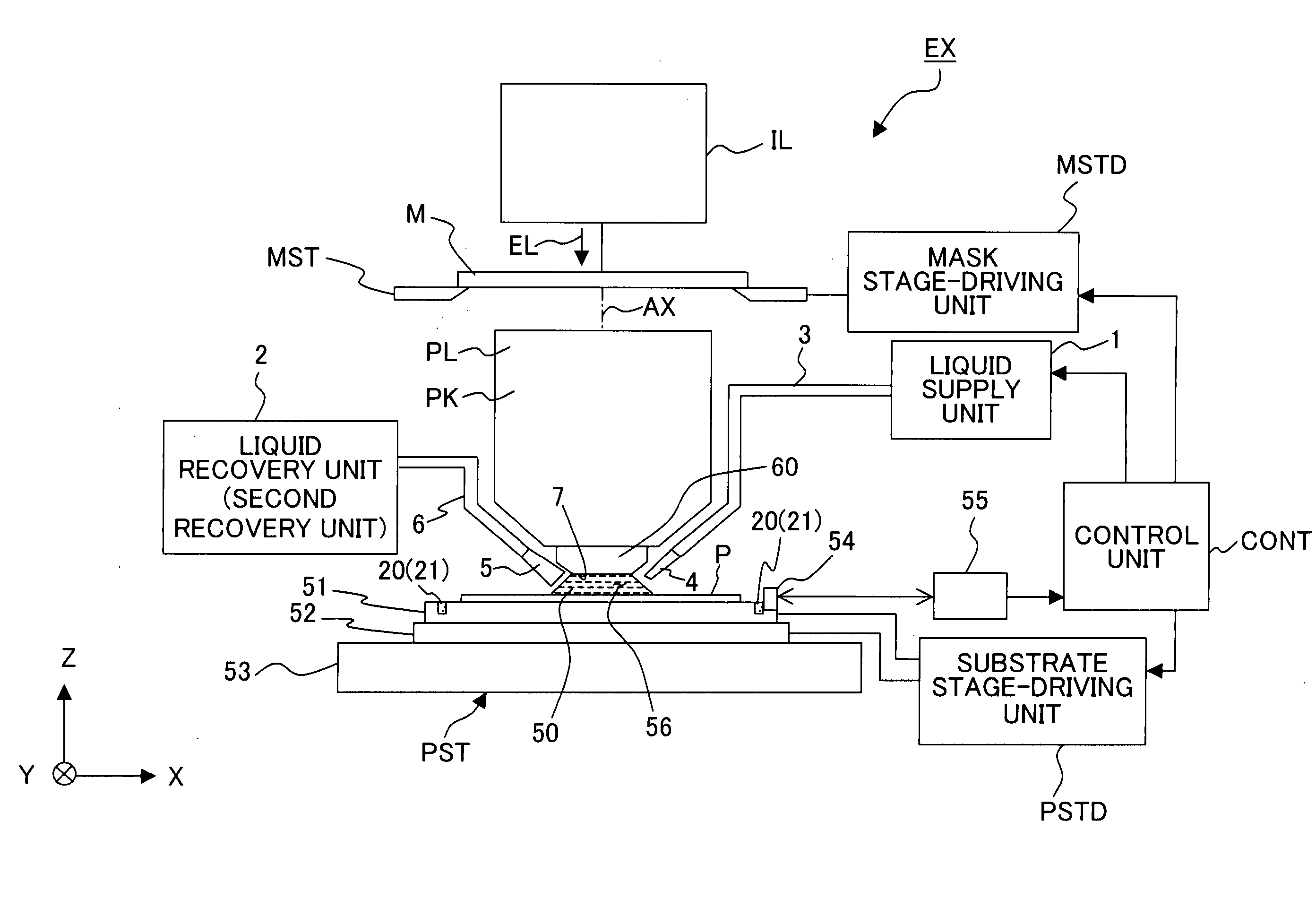
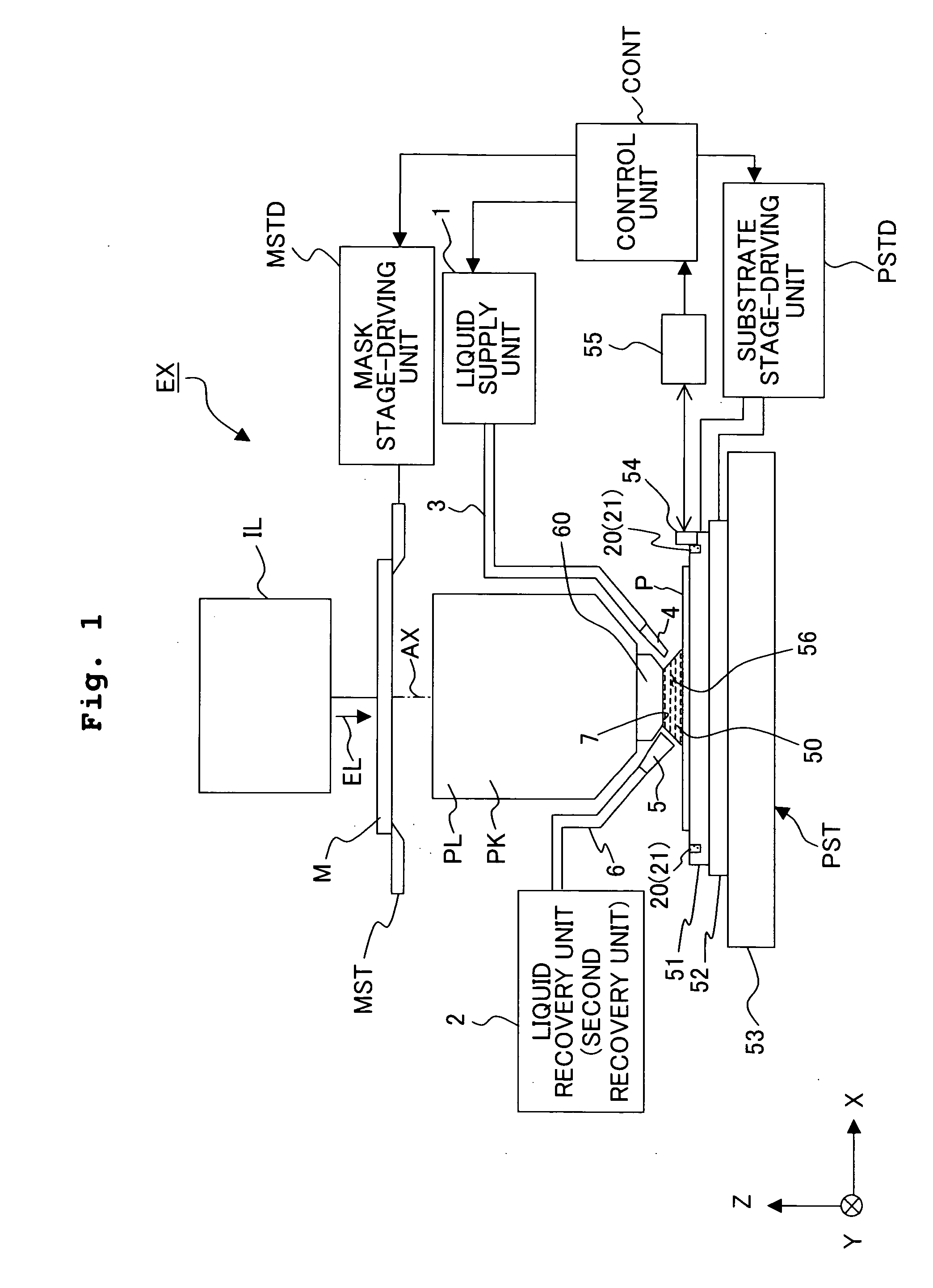
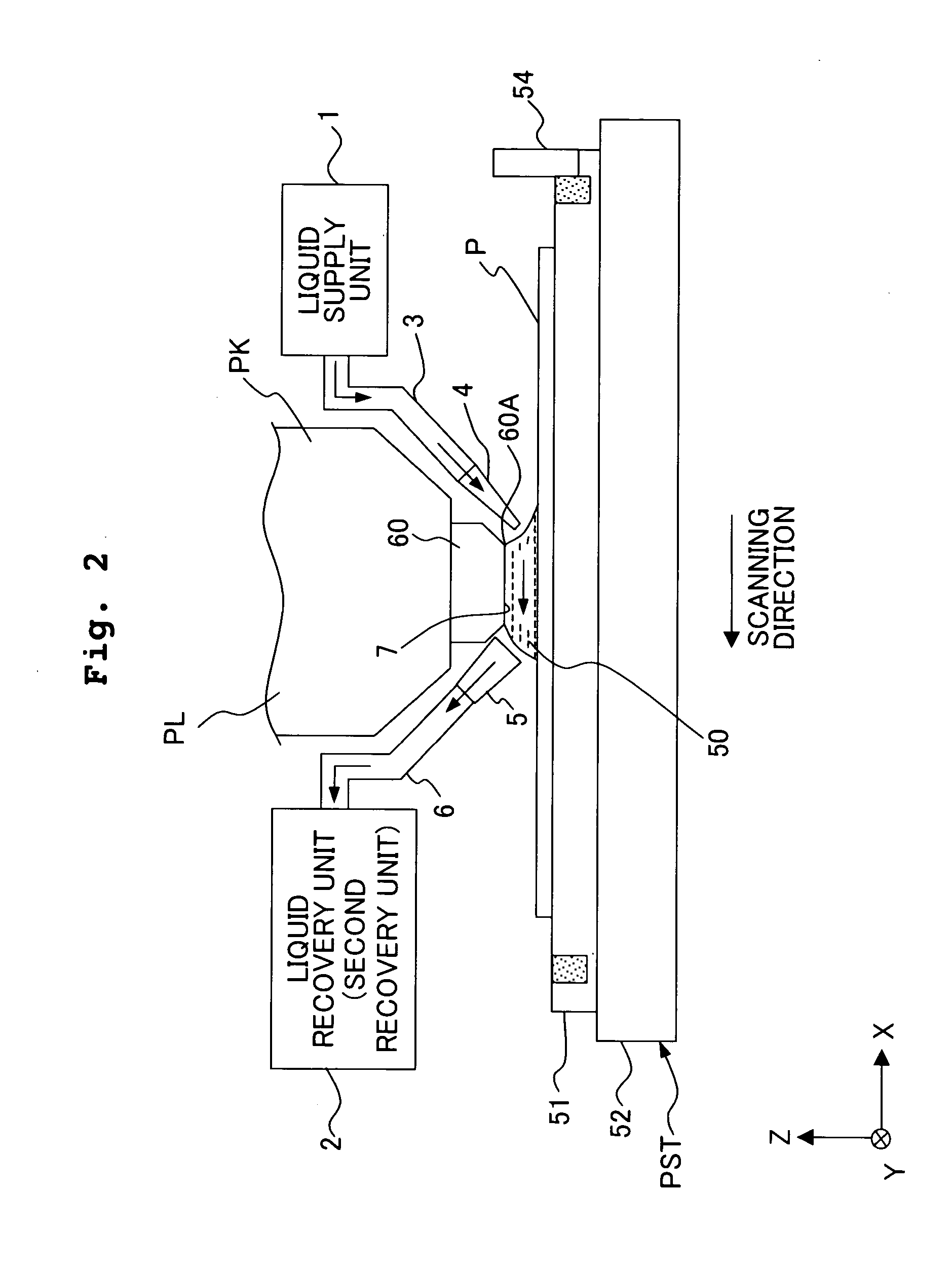
[0051] With reference to FIG. 1, an exposure apparatus EX includes a mask stage MST which supports a mask M, a substrate stage PST which supports a substrate P, an illumination optical system IL which illuminates, with an exposure light beam EL, the mask M supported by the mask stage MST, a projection optical system PL which performs projection exposure for the substrate P supported by the substrate stage PST with an image of a pattern of the mask M illuminated with the exposure light beam EL, a liquid supply unit 1 which supplies a liquid 50 onto the substrate P, a recovery unit 20 which recovers the liquid 50 outflowed to the outside of the substrate P, and a control unit CONT which collectively controls the overall operation of the exposure apparatus EX.

[0052] The embodiment of the present invention will now be explained as exemplified by a case of the use of the scanning type exposure apparatus (so-called scanning stepper) as the exposure apparatus EX in which the substrate P i...

second embodiment

[0090] Next, an explanation will be made with reference to FIG. 7 about another embodiment of the exposure apparatus EX of the present invention. In the following description, the same or equivalent constitutive parts as those of the embodiment described above are designated by the same reference numerals, any explanation of which is simplified or omitted. The characteristic features of this embodiment are that a liquid recovery groove 35 is provided around the substrate P in place of the liquid-absorbing member 21 as the recovery unit and that the substrate stage PST and the tube passage 26 are connectable to one another and separable from each other.

[0091] With reference to FIG. 7, the recovery unit 20 includes the liquid recovery groove 35 which has a predetermined width and which is formed around the auxiliary plate 59 on the Z stage 51. A connecting valve 36 is provided at the end of the flow passage 22. On the other hand, a connecting valve 37, which is connectable and separa...

third embodiment

[0098] An explanation will be made below with reference to FIGS. 8 to 10 about another embodiment of the recovery unit.

[0099] As shown in FIG. 8, the upper surface of the Z stage 51 is inclined, and the upper surface of the holder 57 for holding the substrate P is horizontal. A liquid recovery groove 35 is formed to surround the circumference of the holder 57. In this arrangement, the liquid recovery groove 35 is annular as viewed in a plan view, but the liquid recovery groove 35 is inclined as viewed in a side view. That is, the liquid recovery groove 35 is arranged along the inclination of the upper surface of the Z stage 51. Accordingly, the liquid 50, which outflows to the outside of the substrate P, is spontaneously pooled at an inclined lower section 35A of the liquid recovery groove 35. Accordingly, it is easy to perform the recovery operation for recovering liquid 50 by recovering only the liquid 50 pooled at the inclined lower section 35A.

[0100] As shown in FIG. 9A, the l...


PUM


Abstract

An exposure apparatus exposes a substrate P by locally filling a side of an image plane of a projection optical system PL with a liquid 50 and projecting an image of a pattern onto the substrate P through the liquid 50 and the projection optical system PL. The exposure apparatus includes a recovery unit 20 which recovers the liquid 50 outflowed to the outside of the substrate P. When the exposure process is performed in accordance with the liquid immersion method, the pattern can be transferred accurately while suppressing any environmental change even when the liquid outflows to the outside of the substrate.

Description

CROSS-REFERENCE [0001] This application is a Continuation Application of International Application No. PCT / JP03 / 015666 which was filed on Dec. 8, 2003 claiming the conventional priority of Japanese patent Application Nos. 2002-357958 filed on Dec. 10, 2002 and 2003-296491 filed on Aug. 20, 2003.BACKGROUND OF THE INVENTION [0002] 1. Field of the Invention [0003] The present invention relates to an exposure apparatus for performing the exposure with an image of a pattern projected by a projection optical system in a state in which a space on a side of an image plane of the projection optical system is locally filled with a liquid. The present invention also relates to a method for producing a device by using the exposure apparatus. [0004] 2. Description of the Related Art [0005] Semiconductor devices and liquid crystal display devices are produced with the so-called photolithography technique in which a pattern formed on a mask is transferred onto a photosensitive substrate. The expos...

Claims


Application Information

Patent Timeline
IPC IPC(8): G03F7/20
CPCG03F7/707G03F7/70341G03F7/2041H01L21/0274
Inventor NEI, MASAHIROKOBAYASHI, NAOYUKIARAI, DAIOWA, SOICHI
Owner NIKON CORP
Why Eureka
Try Eureka