Optical element driving apparatus, barrel, exposure apparatus and device manufacturing method

a technology of exposure apparatus and driving apparatus, which is applied in the direction of mountings, printing, instruments, etc., can solve the problems of limited components of optical characteristics that can be corrected, and achieve the effects of high accuracy, fast correction of optical characteristics, and accurate transfer

Inactive Publication Date: 2009-01-08
NIKON CORP
View PDF5 Cites 34 Cited by
  • Summary
  • Abstract
  • Description
  • Claims
  • Application Information

AI Technical Summary

Benefits of technology

[0013]The present invention enables the optical element to be driven in a plurality of directions and enables the optical characteristics of the optical system to be quickly corrected.
[0014]The present invention further provides a barrel or an exposure apparatus that enables the optical characteristics of the optical system to be quickly corrected.
[0015]The present invention further enables a pattern to be accurately transferred onto a substrate with high accuracy, and enables a highly integrated device to be efficiently manufactured with a high yield.

Problems solved by technology

Accordingly, the components of the optical characteristics that can be corrected are limited.

Method used


Image

  • Optical element driving apparatus, barrel, exposure apparatus and device manufacturing method
  • Optical element driving apparatus, barrel, exposure apparatus and device manufacturing method
  • Optical element driving apparatus, barrel, exposure apparatus and device manufacturing method

Examples


first embodiment

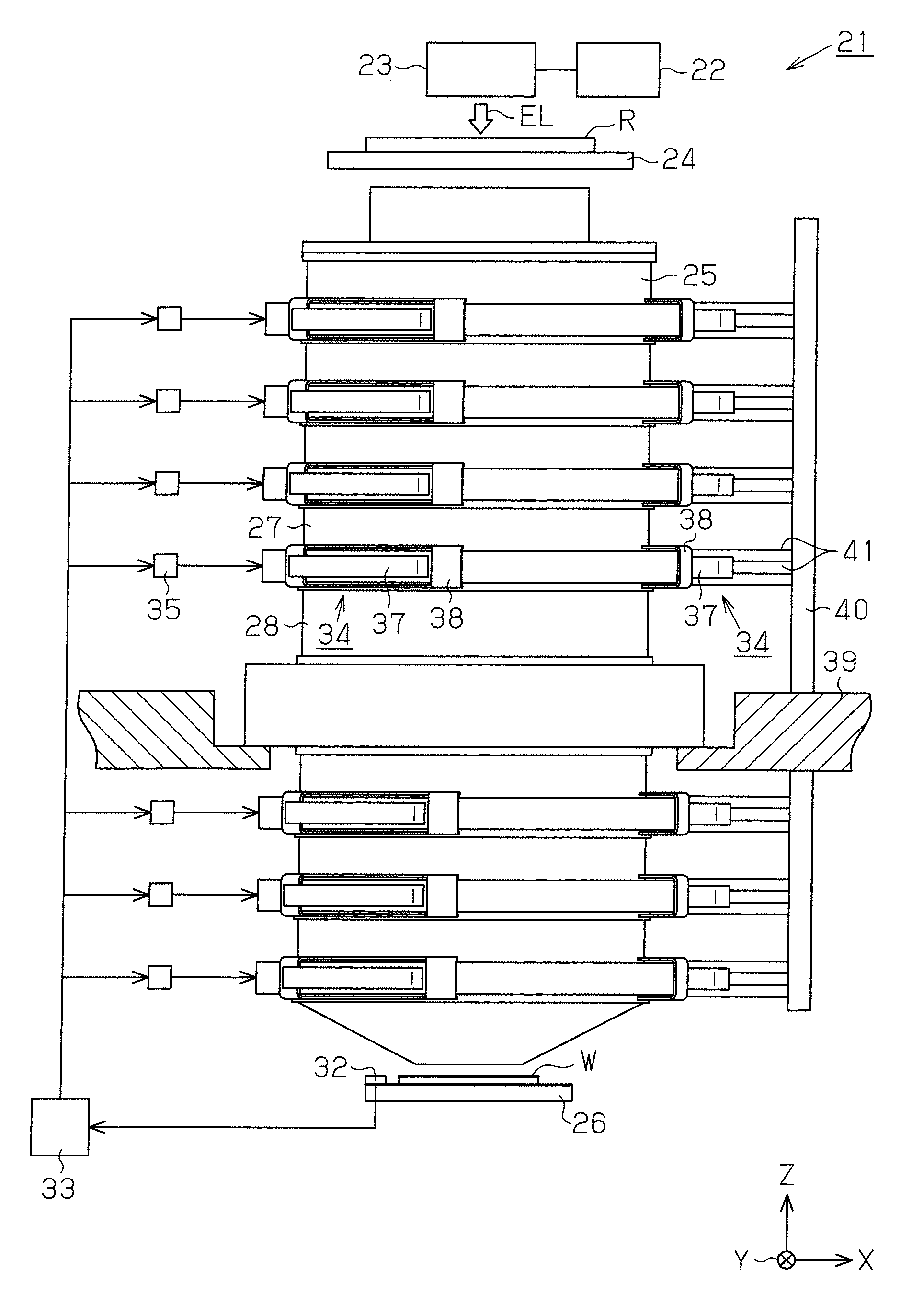
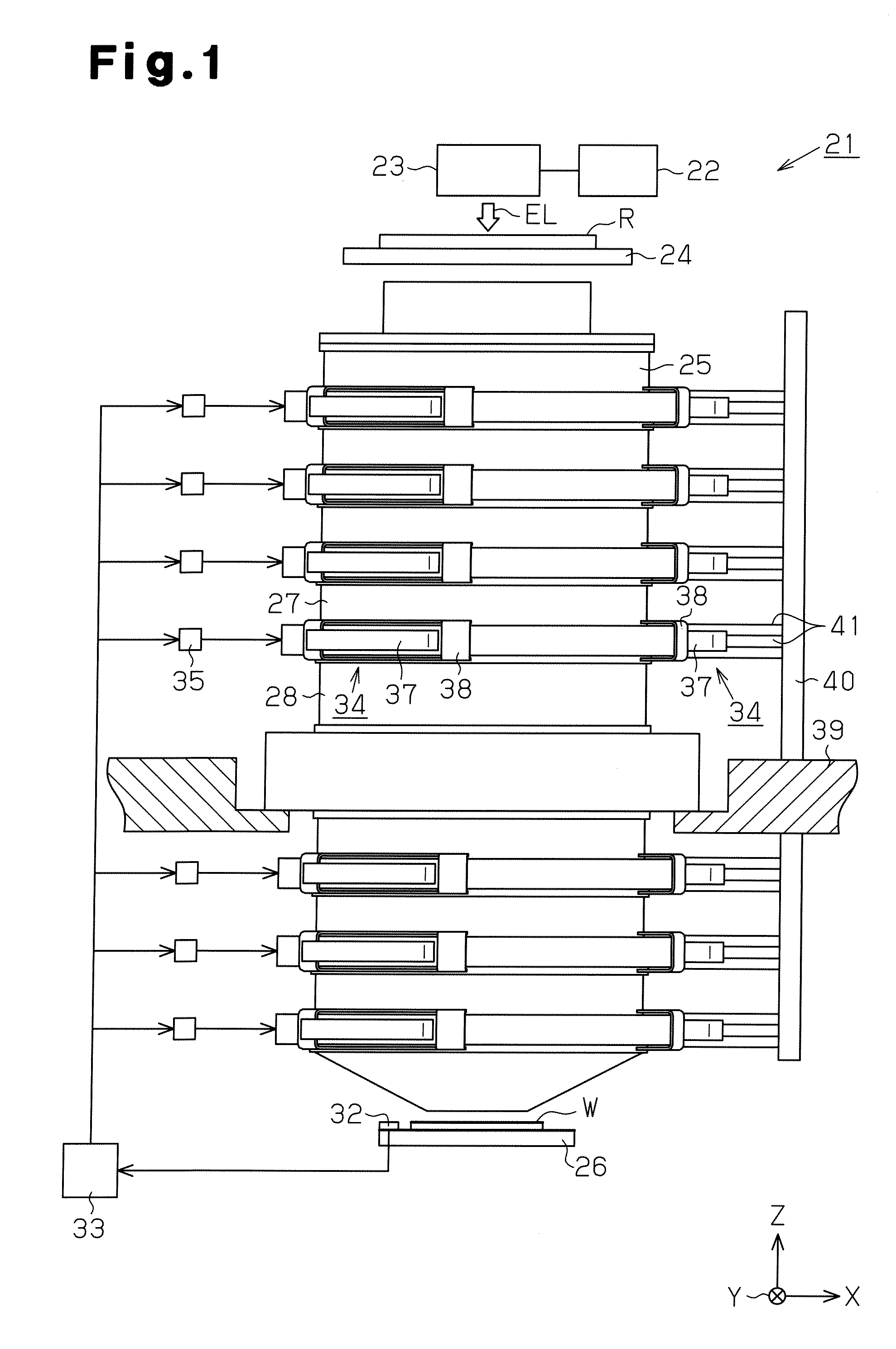
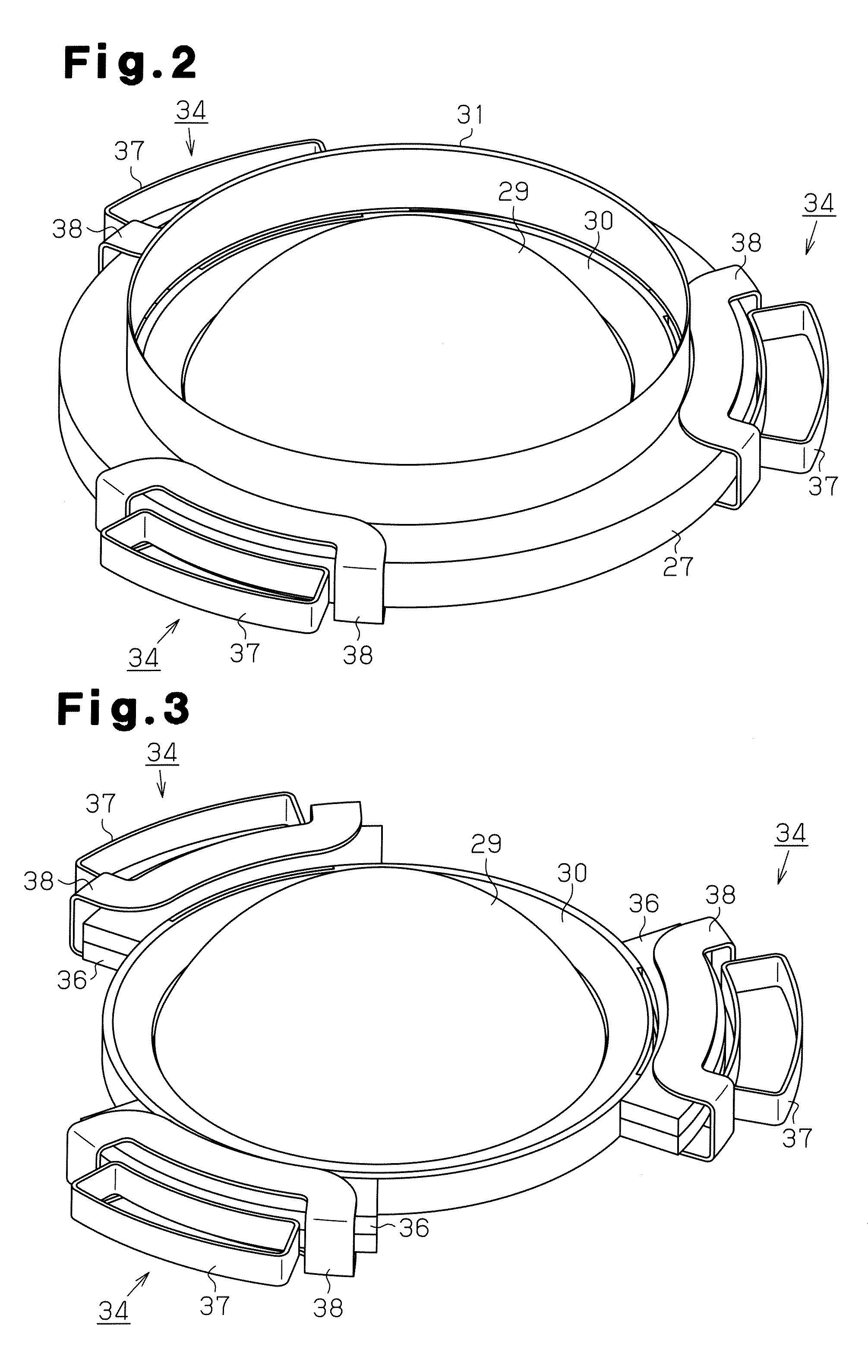
[0027]An exposure apparatus, an optical element driving apparatus, and a barrel of the present invention according to a first embodiment of the present invention will now be described with reference to FIGS. 1 to 6. The exposure apparatus, the optical element driving apparatus, and the barrel are respectively embodied in, for example, an exposure apparatus used to manufacture a semiconductor element, an optical element driving apparatus which drives an optical element, and a barrel accommodating a projection optical system.

[0028]FIG. 1 schematically shows the structure of an exposure apparatus 21. As shown in FIG. 1, the exposure apparatus 21 includes a light source 22, an illumination optical system 23, a reticle stage 24, a projection optical system 25, and a wafer stage 26. The reticle stage 24 holds a reticle R, which may be a photomask. The wafer stage 26 holds a wafer W.

[0029]The light source 22 is, for example, an ArF excimer laser light source. The illumination optical syste...

second embodiment

[0062]A lens driving apparatus 34 according to a second embodiment of the present invention will now be described with reference to FIGS. 7 and 8 mainly focusing on differences from the first embodiment.

[0063]As shown in FIGS. 7 and 8, the lens driving apparatus 34 of the second embodiment includes a first driving unit 51 and a second driving unit 52. The first driving unit 51 drives a lens cell 30 in the optical axis direction. The first driving unit 51 and the second driving unit 52 each include a closed magnetic field type induction motor.

[0064]As shown in FIG. 7, the first driving unit 51 includes a permanent magnet 53, which is arranged on the lens cell 30. The north pole of the permanent magnet 53 faces toward a lens 29, that is, a direction inward the lens cell 30. The south pole of the permanent magnet 53 faces a direction outward from the lens cell 30. In the same manner as in the first embodiment, the permanent magnet 53 is covered by a cover 31. A magnetic inductor 54, wh...


PUM


Abstract

A permanent magnet fixed to a peripheral portion of a lens cell includes two magnets that are joined together so that the north poles face each other and the south poles are exposed. A first driving coil is arranged to face toward exits for lines of magnetic force from the joining surfaces of the north poles of the permanent magnet, and a second driving coil is arranged to face toward entrances for lines of magnetic force in the permanent magnet. The orientation of the lens is adjusted by adjusting the currents supplied to the first driving coil and second driving coil to drive the lens cell in an optical axis direction and horizontal direction in a state in which the lens cell is levitated relative to the cover.

Description

CROSS-REFERENCE TO RELATED APPLICATIONS[0001]This application claims the benefit of Japanese Patent Application No. 2007-126928, filed on May 11, 2007, and U.S. Provisional Application No. 60 / 924,581, filed on May 21, 2007.BACKGROUND OF THE INVENTION[0002]The present invention relates to an optical element driving apparatus which drives an optical element, such as a lens or a mirror. The present invention further relates to a barrel that includes at least one optical element. The present invention further relates to an exposure apparatus used when manufacturing a device, such as a semiconductor element, a liquid crystal display element, or a thin-film magnetic head, and a device manufacturing method.[0003]Such type of an exposure apparatus has optical systems including optical elements, such as a lens and a mirror. The optical elements are held by an optical element holding unit. Among the optical systems included in an exposure apparatus, a projection optical system has adjustable ...

Claims


Application Information

Patent Timeline
Patent Type & Authority Applications(United States)
IPC IPC(8): G02B7/04G02B7/198G03B27/52
CPCG02B7/02G02B7/023G03F7/70825G02B7/1828G02B26/0816G02B7/1821G03F7/70008G03F7/70316G02B7/04
Inventor ARAI, YOICHI
Owner NIKON CORP
Why Eureka
Try Eureka