System and method for the acoustic loading of an analytical instrument using a continuous flow sampling probe

a technology of continuous flow sampling and system and method, which is applied in the field of systems and methods for transporting fluid samples to an analytical instrument, can solve the problems of increasing sampling speed at the cost of sensitivity, increasing sample loading time, and still required sample separation, etc., and achieves high repetition rate, rapid sample processing and generation of droplets

Active Publication Date: 2020-09-08
DH TECH DEVMENT PTE +1
View PDF15 Cites 31 Cited by
  • Summary
  • Abstract
  • Description
  • Claims
  • Application Information

AI Technical Summary

Benefits of technology

[0029]In acoustic ejection, an acoustic ejector directs focused acoustic energy into a reservoir containing a fluid sample in a manner that results in the ejection of discrete fluid droplets from the fluid surface. Acoustic ejection provides many advantages over other droplet generation methodologies. For instance, acoustic fluid ejection devices are not subject to clogging, misdirected fluid, or improperly sized droplets, and acoustic technology does not require the use of tubing or any invasive mechanical action. Acoustic ejection technology as described, for example, in U.S. Pat. No. 6,802,593 to Ellson et al., enables rapid sample processing and generation of droplets in the nanoliter or even picoliter range. In addition, acoustic ejection enables control over droplet size as well as repeated generation of consistently sized droplets. See U.S. Pat. No. 6,416,164 to Stearns et al., incorporated by reference herein. As explained in that patent, the size of acoustically ejected droplets from a fluid surface can be carefully controlled by varying the acoustic power, the acoustic frequency, the toneburst duration, and / or the F-number of the focusing lens.
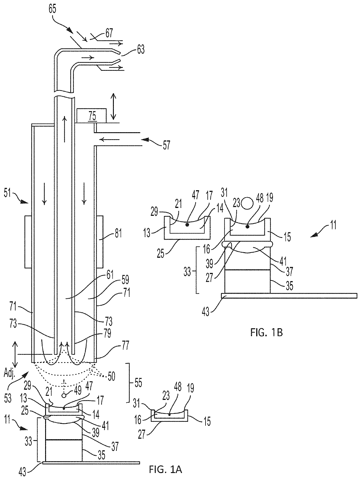
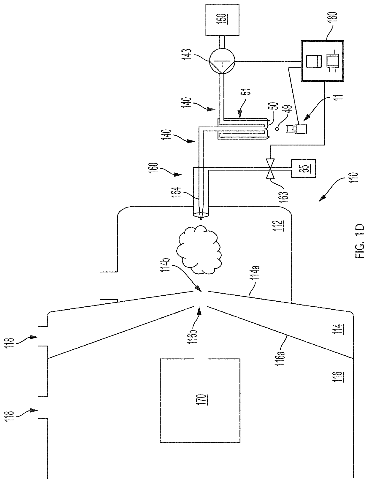
[0030]The invention achieves numerous advantages over prior methods and systems for loading fluid samples into an analytical device such as a mass spectrometer. The use of ADE to eject sample droplets into the sampling interface of a continuous flow sampling probe, as provided herein, enables accurate and precise transfer of ultra-monodisperse nanoliter-sized droplets at a high repetition rate, on the order of 250 Hz, or higher, when the droplets are acoustically ejected in succession from the same fluid reservoir. This allows for “injection” of a known but variable volume of a fluid sample into the system for analysis. In addition, the present system can be adapted to provide for a very rapid transition between reservoirs, in turn enabling extremely rapid high throughput sample processing; use in conjunction with high molecular weight analytes, such as peptides and proteins; minimal or no carryover, as ADE transfer is touchless and the flow probe is self-cleaning; matrix independence, as analyte diffusion and mixing in the flow probe solvent eliminates matrix suppression issues at the single droplet level, even when the sample is undiluted plasma; quantitation with excellent dynamic range, linearity, limit of detection, and limit of quantitation; and kinetic measurements in real time by sampling a single source well over time at single-drop resolution using a high repetition rate droplet stream. In a preferred embodiment, the invention makes use of active flow control, by applying process control principles to actively manage the fluid interface at the probe sampling tip and thereby optimize conditions for sample loading and analysis as will be explained infra.

Problems solved by technology

Despite these improvements, the time required for sample separation is still around one minute.
Even if real separation is not required, the mechanics of loading samples into the mass spectrometer still limit sample loading time to about ten seconds per sample.
However, the increase in sampling speed comes at the cost of sensitivity.
Processing samples in parallel using multiplexed chromatography systems can increase throughput, but the complexity of this approach can negatively impact system reliability and often preclude its use in high throughput screening (HTS) environments.
However, application of LDTD in the literature has been mainly aimed at small drug-like molecules, as the thermal nature of this technique and the use of an ambient pressure chemical ionization (APCI) system make it unsuitable for both modified peptides and cellular metabolites in biochemical screening.
Another limitation of current mass spectrometer loading processes is the problem of carryover between samples, which necessitates a cleaning step after each sample is loaded to avoid contamination of a subsequent sample with a residual amount of analyte in the prior sample.
This requires time and adds a step to the process, complicating rather than streamlining the analysis.
Additional limitations of current mass spectrometers when used to process complex samples, such as biological fluids, are unwanted “matrix effects,” phenomena that result from the presence of matrix components (e.g., natural matrix components such as cellular matrix components, or contaminants inherent in some materials such as plastics) and adversely affect detection capability, precision, and / or accuracy for the analyte of interest.
While the sensitivity and speed of the ADE-based process were significant, and capable of supporting high-throughput screening, IC50 determination, and kinetic studies, some limitations remained.
In particular, as noted by Sinclair et al., potential matrix effects can still be problematic.
Additionally, for applications in which a consistent droplet size is necessary or desirable, the acoustic mist approach is less than ideal, insofar as droplets with different sizes are generated by a single acoustic burst.

Method used


Image

  • System and method for the acoustic loading of an analytical instrument using a continuous flow sampling probe
  • System and method for the acoustic loading of an analytical instrument using a continuous flow sampling probe
  • System and method for the acoustic loading of an analytical instrument using a continuous flow sampling probe

Examples


example 1

[0112]This example describes how the flow configuration at the open port of the probe correlates with the ion peaks obtained in a real-time mass spectrometric (MS) evaluation. In this experiment, source wells were loaded with 50 μL of reserpine, as analyte (Sigma-Aldrich, St. Louis, Mo.) at a concentration of 100 nM in 50:50 MeOH:H2O. The flow probe was positioned above the source well at a distance of approximately 10 mm, aligned to center the flow probe over the source well, and oriented so that the open port of the flow probe captured droplets acoustically ejected vertically upward from the source well. The carrier solvent in the flow probe was 100% methanol and the solvent flow rate in the tubing annulus was varied from 40 μL / min to 55 μL / min by adjusting the active flow control solvent pump. The flow rate of solvent into the inner capillary tube was fixed by the gas flow of the aspirating nebulizer at the mass spectrometer input.

[0113]2.5 nL droplets were acoustically ejected o...

example 2

[0114]The source wells were filled with 50 μL of analyte 1 nM reserpine in a matrix of 50% MeOH:H2O and the flow probe solvent flow rate adjusted to produce a pendant drop of 100% MeOH at the tip of the flow probe. The ADE system was calibrated to eject 2.5 nL droplets with repetition rates adjusted from 1 Hz to 200 Hz.

[0115]As shown in the mass spectra of FIG. 4A, single 2.5 nL droplets of 1 nM reserpine (2.5 attomol) are below LOQ in the pendant drop mode. Referring to FIG. 4B, a sample composed of five droplet injections (12.5 nL in total; all within one second) was analyzed and demonstrated good reproducibility with respect to peak shape, with a peak width typically less than 30 seconds. As illustrated in FIGS. 4C-4G, peak area was found to increase approximately linearly with the number of droplet injections per second over the full range of 5 droplet injections per second to 200 droplet injections per second, although small variations in the size of the pendant droplet were fo...

example 3

[0116]In this example, the method of Example 1 was repeated except that the solvent pump flow rate was adjusted to operate the flow probe in vortex mode, with 10 nM reserpine analyte and a matrix of 50% MeOH:H2O in the source well. Referring to FIG. 5A, in this case single droplet injections (2.5 nL×10 nM=25 attomol) were found to give clear MS peaks with a two-second width at baseline. Referring to FIGS. 5B-5D, the peaks obtained were consistently narrow (less than about 5 seconds at baseline) for injections of up to 25 droplets in one second. FIGS. 5E-G illustrate resulting peaks for 50, 100, and 200 droplet injections per second for comparison.

[0117]The relationship between peak shape and injection time was evaluated, where the injection time is the time period between the first droplet ejection and the last droplet ejection within a single multi-droplet ejection event. 50 droplets were transferred over a range of injection times from 0.125 to 5 seconds, in vortex mode. FIG. 6 pr...


PUM


Abstract

A system and method are provided for loading a sample into an analytical instrument using acoustic droplet ejection (“ADE”) in combination with a continuous flow sampling probe. An acoustic droplet ejector is used to eject small droplets of a fluid sample containing an analyte into the sampling tip of a continuous flow sampling probe, where the acoustically ejected droplet combines with a continuous, circulating flow stream of solvent within the flow probe. Fluid circulation within the probe transports the sample through a sample transport capillary to an outlet that directs the analyte away from the probe to an analytical instrument, e.g., a device that detects the presence, concentration quantity, and / or identity of the analyte. When the analytical instrument is a mass spectrometer or other type of device requiring the analyte to be in ionized form, the exiting droplets pass through an ionization region, e.g., an electrospray ion source, prior to entering the mass spectrometer or other analytical instrument. The method employs active flow control and enables real-time kinetic measurements.

Description

CROSS-REFERENCE TO RELATED APPLICATIONS[0001]This application claims priority under 35 U.S.C. § 119(e)(1) to Provisional U.S. Patent Application Ser. No. 62 / 590,079, filed Nov. 22, 2017 and incorporated by reference herein.TECHNICAL FIELD[0002]The present invention relates generally to systems and methods for transporting a fluid sample to an analytical instrument, and more particularly relates to such systems and methods that that make use of a continuous flow sampling probe. The invention finds utility in the fields of analytical chemistry, biological tresearch, and medicine.BACKGROUND[0003]Accurate determination of the presence, identity, concentration, and / or quantity of an analyte in a sample is critically important in many fields. Many techniques used in such analyses involve ionization of species in a fluid sample prior to introduction into the analytical equipment employed. The choice of ionization method will depend on the nature of the sample and the analytical technique u...

Claims


Application Information

Patent Timeline
Patent Type & Authority Patents(United States)
IPC IPC(8): H01J49/04H01J49/00H01J49/16B01L3/02
CPCH01J49/165H01J49/0454H01J49/0404B01L3/0268H01J49/0031B01L2400/0439G01N29/222G01N29/02B01L2400/0436H01J49/045H01J49/0445
Inventor DATWANI, SAMMYARNOLD, DON W.GHISLAIN, LUCIEN P.LIU, CHANGCOVEY, THOMAS
Owner DH TECH DEVMENT PTE
Why Eureka
Try Eureka