
Methods and Apparatus for Rendering Focused Plenoptic Camera Data using Super-Resolved Demosaicing

a technology of focused plenoptic camera and super-resolved demosaicing, which is applied in the direction of picture signal generators, solid-state device signal generators, television systems, etc., can solve the problems of damage to subpixel displacement information implicitly present in input images, and the modification of very sensitive subpixel positional data by conventional demosaicing

Active Publication Date: 2013-05-23
ADOBE SYST INC
View PDF11 Cites 207 Cited by
  • Summary
  • Abstract
  • Description
  • Claims
  • Application Information

AI Technical Summary

Benefits of technology

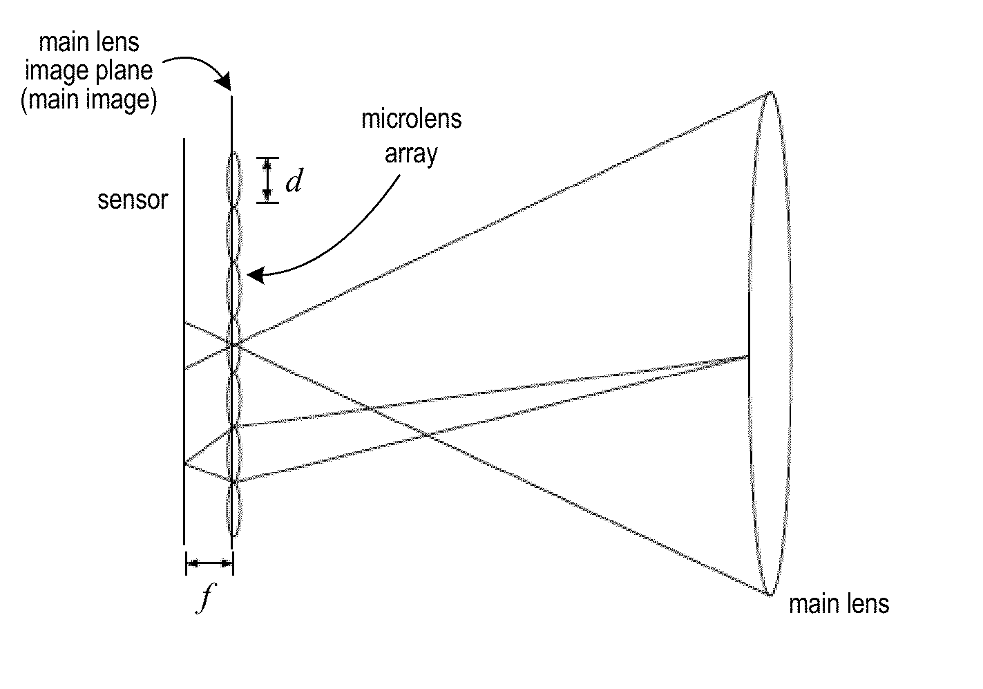
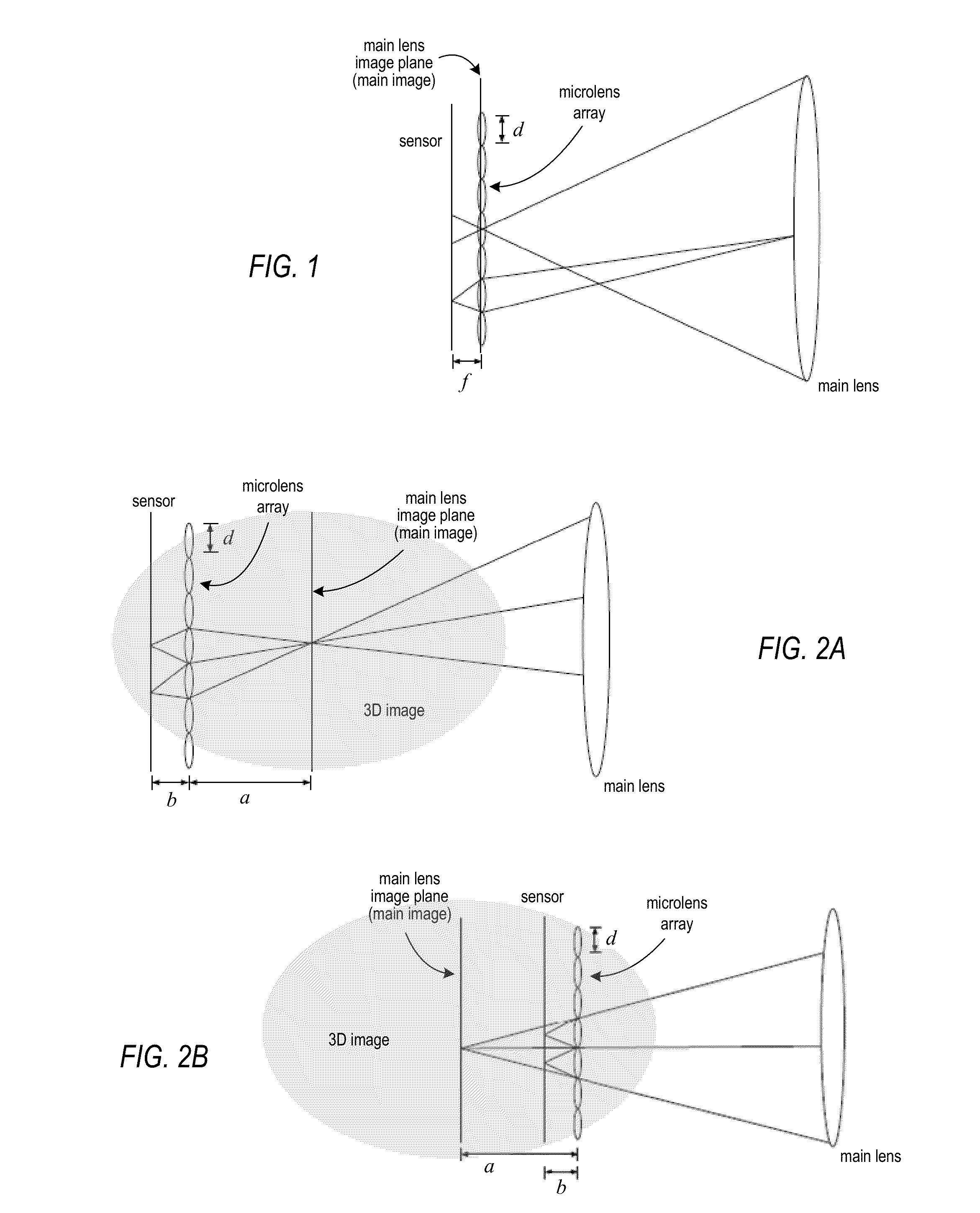
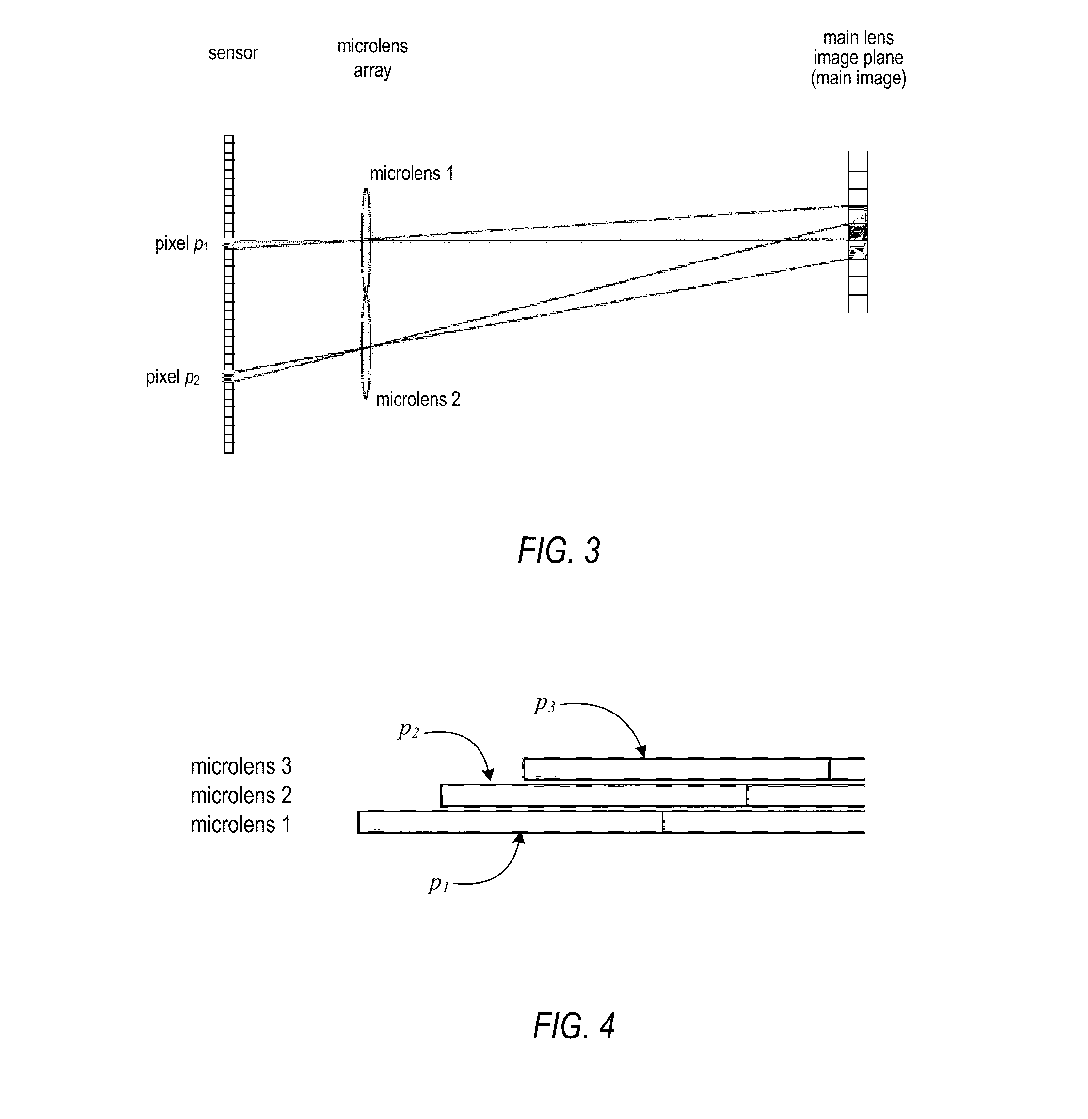
The patent describes methods and apparatus for rendering focused plenoptic camera data using demosaicing super-resolution. The focused plenoptic camera works as an array of microcameras that capture images with a higher resolution than conventional plenoptic cameras. The camera uses a demosaicing technique to convert color images, which may damage the sensitive subpixel positional data. The patent describes a super-resolved demosaicing technique that performs simultaneous super-resolution and demosaicing, allowing for improved spatial resolution. The technique also includes a depth of focus adjustment for the microimages and deconvolution to generate the output super-resolved image. The technical effects of the patent include improved image quality and higher resolution capture using a focused plenoptic camera.

Problems solved by technology

However, conventional demosaicing modifies the very sensitive subpixel positional data.
In more detail, conventional demosaicing effectively shifts all four pixels (e.g., Red, Green, Green, Blue in a typical Bayer array) to put them in the same location, which may damage subpixel displacement information implicitly present in the input image.

Method used


Image

  • Methods and Apparatus for Rendering Focused Plenoptic Camera Data using Super-Resolved Demosaicing
  • Methods and Apparatus for Rendering Focused Plenoptic Camera Data using Super-Resolved Demosaicing
  • Methods and Apparatus for Rendering Focused Plenoptic Camera Data using Super-Resolved Demosaicing

Examples


example results

[0109]The example images presented in FIGS. 10 through 19 were generated using an example focused plenoptic camera implementation and selecting n=8 in Table 2 for 3×3 super-resolution, corresponding to a distance a=13.6 mm in front of the microlenses for this example camera. A relatively large value of n was used because, for lower values of n, the image may be too far from the microlenses and may be too small.

[0110]In the example focused plenoptic camera implementation used to capture these example images, the main camera lens is moved forward with a 13 mm extension tube and, the position of the main lens is fine-tuned by changing the focus. Refocusing provides fine-tuning by continuously moving the lens forward between 0 mm and 10 mm. Super-resolution was performed at a shift of A+n=82 pixels between captured microimages.

[0111]For the example focused plenoptic camera implementation, a medium format camera, using an 80-mm lens and a 39-megapixel digital back, is used. Pixel size is...

example implementations

of Rendering Methods

[0160]Embodiments of the super-resolved demosaicing technique may be performed by a rendering module implemented by program instructions stored in a computer-readable storage medium and executable by one or more processors (e.g., one or more CPUs or GPUs) of a computer system or other device. FIG. 44 illustrates a rendering module that may render images from flats captured by various embodiments of a focused plenoptic camera. Rendering module 920 may, for example, implement super-resolved demosaicing methods as illustrated in FIGS. 21 through 33. FIG. 45 illustrates an example computer system on which embodiments of rendering module 920 may be implemented. In some embodiments of a focused plenoptic camera, rendering module 920 may be implemented in the camera, e.g. in a captured data processing module. Referring to FIG. 44, rendering module 920 receives an input flat 910 captured by a focused plenoptic camera. An example portion of a flat as may be captured by va...


PUM


Abstract

A super-resolved demosaicing technique for rendering focused plenoptic camera data performs simultaneous super-resolution and demosaicing. The technique renders a high-resolution output image from a plurality of separate microimages in an input image at a specified depth of focus. For each point on an image plane of the output image, the technique determines a line of projection through the microimages in optical phase space according to the current point and angle of projection determined from the depth of focus. For each microimage, the technique applies a kernel centered at a position on the current microimage intersected by the line of projection to accumulate, from pixels at each microimage covered by the kernel at the respective position, values for each color channel weighted according to the kernel. A value for a pixel at the current point in the output image is computed from the accumulated values for the color channels.

Description

PRIORITY INFORMATION[0001]This application claims benefit of priority of U.S. Provisional Application Ser. No. 61 / 377,821 entitled “Methods and Apparatus for Rendering Focused Plenoptic Camera Data using Super-Resolved Demosaicing” filed Aug. 27, 2010, the content of which is incorporated by reference herein in its entirety.BACKGROUNDDescription of the Related Art[0002]In contrast to conventional cameras, light-field, or radiance capturing, cameras sample the four-dimensional (4-D) optical phase space or light-field, and in doing so capture information about the directional distribution of the light rays. This information captured by light-field cameras may be referred to as the light-field, the plenoptic function, or radiance. In computational photography, a light-field is a 4-D record of all light rays in 3-D. Radiance describes both spatial and angular information, and is defined as density of energy per unit of area per unit of stereo angle (in radians). A light-field camera cap...

Claims


Application Information

Patent Timeline
Patent Type & Authority Applications(United States)
IPC IPC(8): H04N5/228H04N23/40
CPCH04N5/23229H04N9/045H04N23/60H04N23/80H04N23/843H04N25/134H04N23/957H04N23/951
Inventor GEORGIEV, TODOR G.CHUNEV, GEORGI N.
Owner ADOBE SYST INC
Learn More