Thermal transfer printer

Inactive Publication Date: 2001-01-02
IMPERIAL CHEM IND LTD
View PDF10 Cites 33 Cited by
  • Summary
  • Abstract
  • Description
  • Claims
  • Application Information

AI Technical Summary

Benefits of technology

This roll fed receiver enables much larger supplies of receiver sheet to be used. Thus the number of blank sheets that a cut sheet fed printer can hold at one time is limited, by conventional design, to approximately 100 repeats. These limitations are centred around maintaining contact between the top of the receiver stack and the receiver infeed roller, as the stack size reduces. The present roll fed printers have the capability of holding sufficient media (donor sheet and receiver sheets), to produce much larger numbers of images. e.g. 1000, before media replenishment is required. This can be a significan

Problems solved by technology

However, such printers are not well adapted for general use in photo booths an

Method used


Image

  • Thermal transfer printer
  • Thermal transfer printer
  • Thermal transfer printer

Examples


Embodiment Construction

The invention is further described with reference to a specific embodiment shown in the accompanying drawings, wherein:

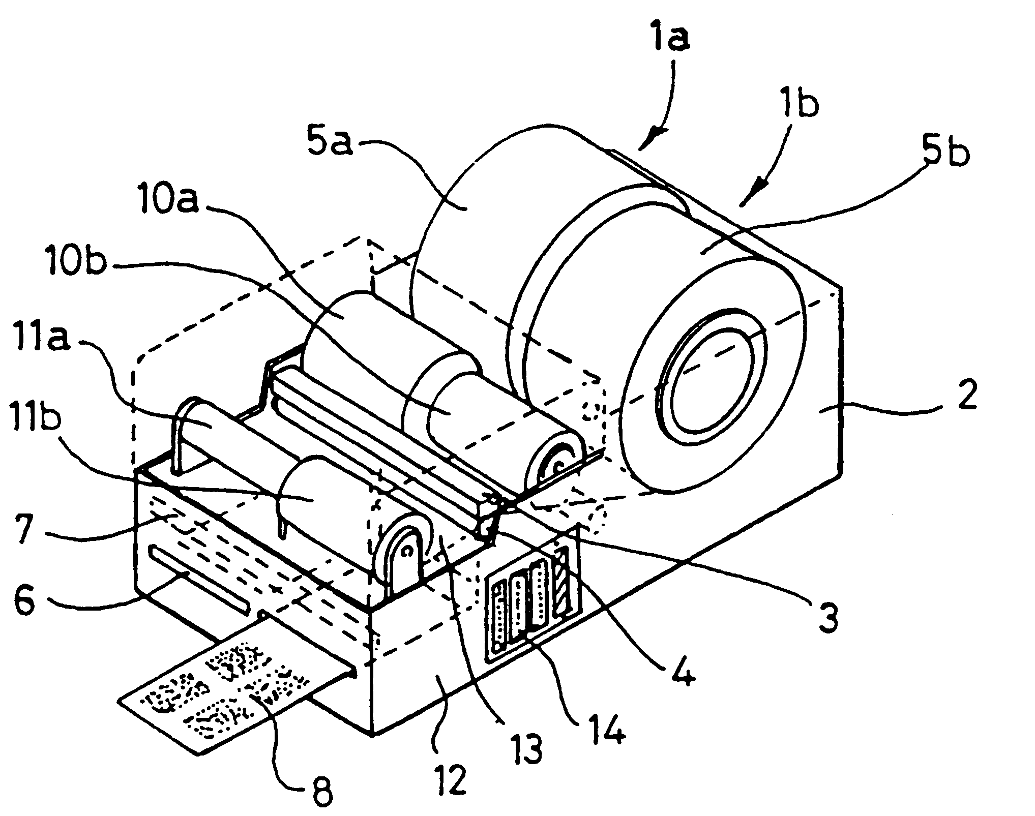
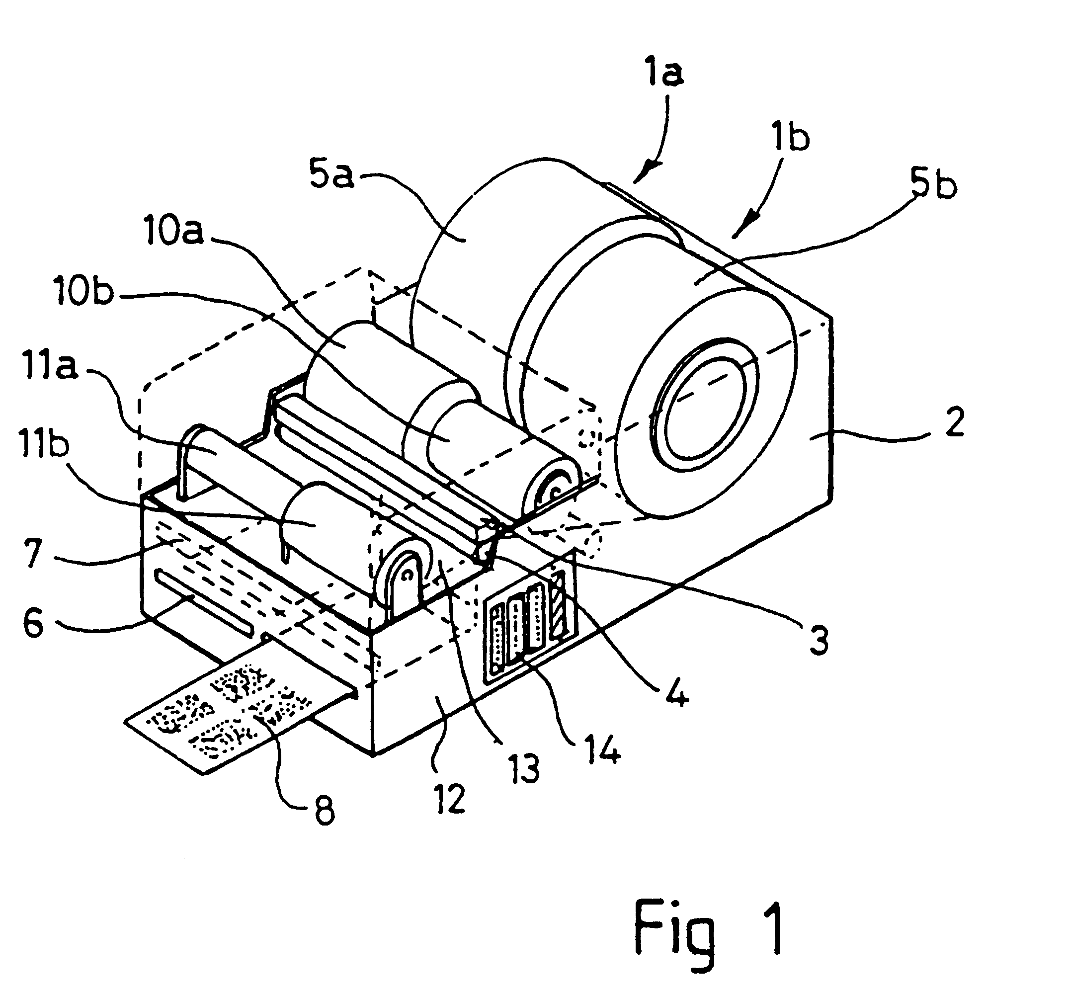
FIG. 1 is an isometric sketch showing the basic outline of a high volume dye diffusion printer according to the invention;

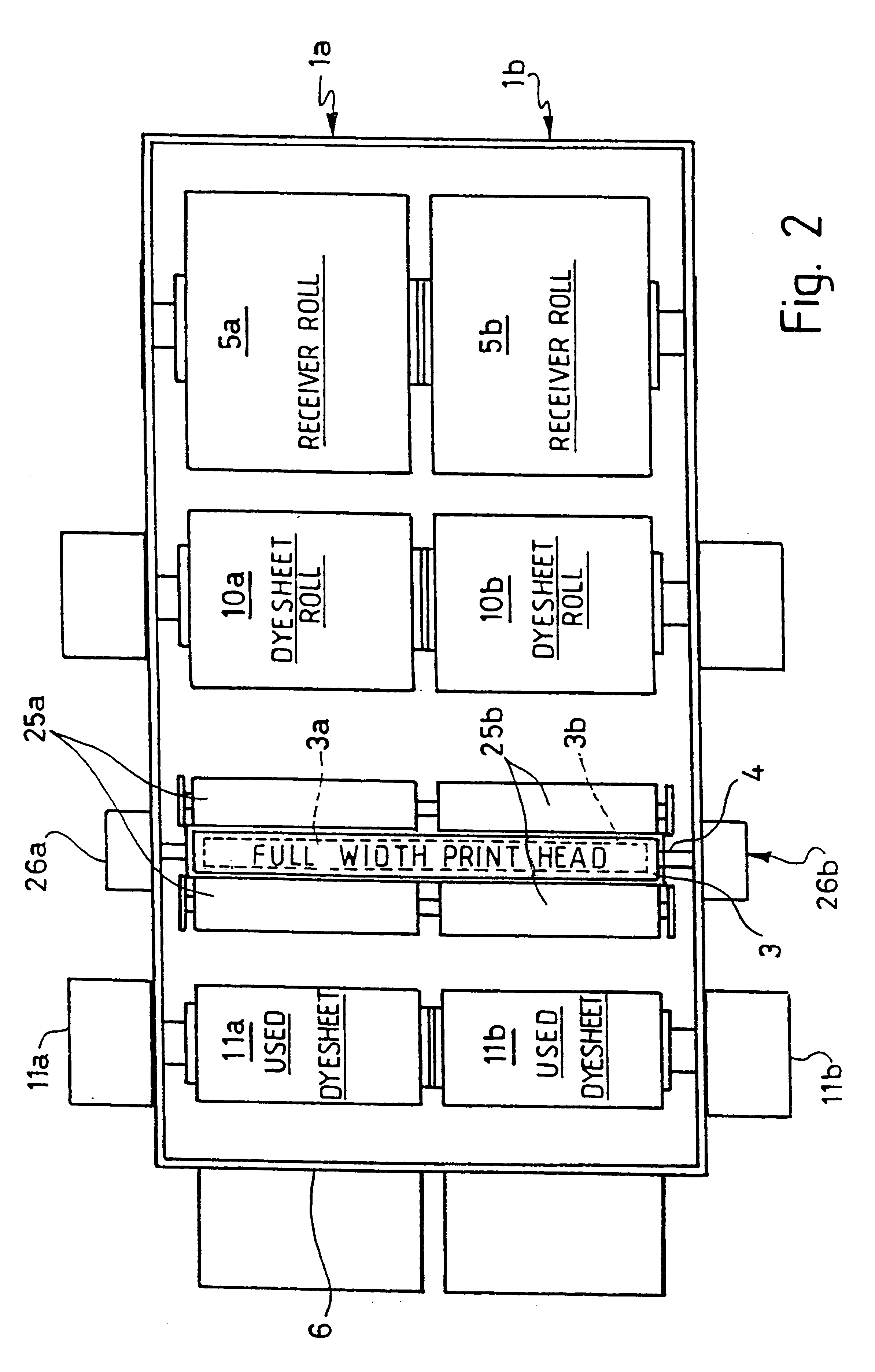
FIG. 2 is a somewhat diagrammatic plan view of the printer;

FIG. 3 is a somewhat diagrammatic cross-sectional view taken through the printer; and

FIG. 4 is a logic diagram.

Referring to the drawings, the printer comprises two parallel A6 engines 1a and 1b mounted within a single chassis 2 and capable of independent or dual simultaneous usage. A single A4 printhead 3 and head actuation assembly extends the full width of the chassis, and straddles both print engines. The printhead 3 has two sets of heating elements, 3a, 3b, one for each engine. Below the printhead is a split platen roller 4, centrally supported to minimise deflection caused by the applied printhead pressure during printing. Each of the two parts of the split platen roller is separatel...


PUM


Abstract

A thermal transfer printer comprises two parallel and adjacent print engines (1a, 1b), with each engine comprising a platen roller (4), a donor ribbon extending from a supply spool (10a, 10b) to a take-up spool (11a, 11b), and receiver supply rolls (5a, 5b) to hold a supply of receiver sheet. Drive means (11a, 11b; 26a, 26b) transport the donor ribbon and receiver sheet through the engine during printing independently from the drive means of the other engine. A printhead (3) has a row of heaters extending across both engines, with a first set (3a) of heaters positioned to operate with the first engine (1a) and a second set (3b) of heaters positioned to operate with the second engine (1b). Control means coordinate activation of the engines selectively with application of the image signal to the heater set which is operable with that selected engine. Both engines can be operated independently, enabling the printer to be set up for independent or dual printing.

Description

This application is the national phase of international application PCT / GB98 / 00286 filed Jan. 30, 1998 which designated the U.S.The invention relates to thermal transfer printers, and especially to thermal transfer printers useful for service in photo booths.BACKGROUND TO THE INVENTIONThermal transfer printing is a process for generating printed images by transferring thermally transferable colorant from a thermal transfer donor sheet to a receiver. Donor sheets comprise a base film coated on one side with a transfer coat, the latter comprising either a non-transferable binder containing one or more thermally transferable dyes for dye diffusion or sublimation transfer, or an ink of colorant and fusible binder which also transfers with the colorant. Printing is effected by heating selected areas of the donor sheet while the transfer coat is pressed against the surface of the receiver, thereby to transfer the dyes or inks from those selected areas to corresponding areas of the receive...

Claims


Application Information

Patent Timeline
IPC IPC(8): B41J15/18B41J3/00B41J3/42B41J3/62B41J3/54B41J2/325
CPCB41J3/42B41J3/62B41J15/18
Inventor LEVER, PHILIP EGODDARD, KENT CPORTUS, ROBERT T
Owner IMPERIAL CHEM IND LTD
Why Eureka
Try Eureka