System and method for calibrating an optical reader system

Active Publication Date: 2010-06-24
IGT GLOBAL SOLUTIONS CORP
View PDF4 Cites 3 Cited by
  • Summary
  • Abstract
  • Description
  • Claims
  • Application Information

AI Technical Summary

Benefits of technology

[0018]In another application, bins for each gray scale area are formed by the digital numbers from the ADCs for the expected reflected light from each gray scale area. Histogram are formed for each bin of the number of pixels in each bin. Illustratively, when the LED drive currents are at the high end of the expected linear range, the light reflected from each of the gray scale areas will exceed expectations. The histogram of p

Problems solved by technology

LEDs and photo-transistors are non-linear, but both have limited areas where their responses are reasonably linear.
LED characteristics, however, may change ove

Method used


Image

  • System and method for calibrating an optical reader system
  • System and method for calibrating an optical reader system
  • System and method for calibrating an optical reader system

Examples


Example

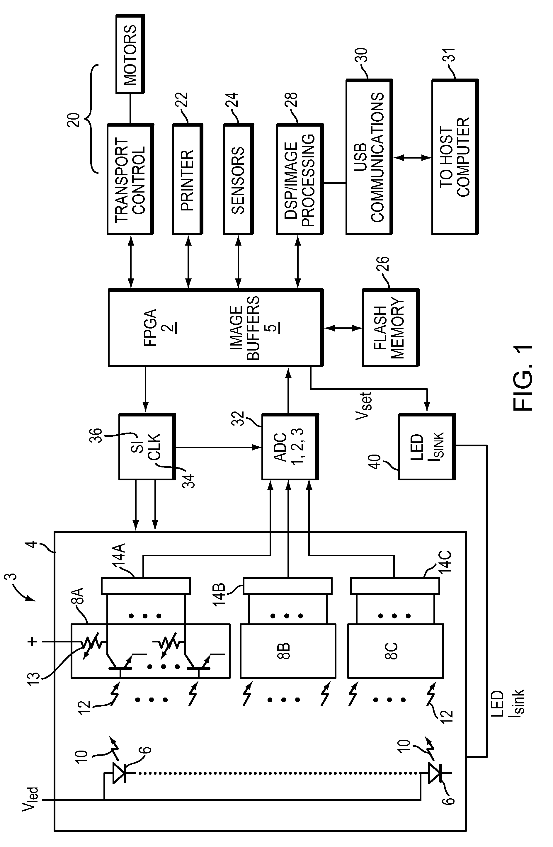
[0037]FIG. 1 is a block diagram schematic representation of an optical reader system incorporating the present invention. FIG. 1 illustrates an optical reader 3 of LEDs (light emitting diodes) 6 and three banks of photo-transistors 8A, 8B, and 8C. Additional optics, electronics and hardware that are employed in conjunction with the present invention, and known to those skilled in the art, are not shown in FIG. 1, and are only inferentially discussed herein.

[0038]A FPGA 2 (field programmable gate array) controls the reader 3. The reader 3 includes a bar (not shown) mounting a row of LEDs 6 that extends horizontally across a document (not shown) to be read. The bar also mounts a row of photo-transistors arranged in three groups, 8A, 8B and 8C, respectively. Illustratively, each group of photo-transistors 8A, 8B, 8C contains 576 photo-transistors or, collectively (in this application) 1728 photo-transistors, where each photo-transistor constitutes one pixel (picture element). If a shee...


PUM


Abstract

A method and system for calibrating optical reader systems employs a target with areas comprising linear gray scale levels. The gray scale levels include the darkest and the lightest scenes. The gray scale levels are illuminated by an array of LEDs and the light reflected from target impacts photo-transistors. The photo-transistors are biased in their linear ranges and the target is scanned while the LED drive current is changed. The photo-transistor responses to the different gray scale levels at the different LED drive currents are analyzed, and the LED rive current that produces a linear output from the photo-transistors over the gray scale dynamic range is selected. Several video channels may be used and their offsets and gains are normalized. Black offsets and black to white gain correction functions are generated for balancing or correcting each pixel. The correction functions may be applied by a processor for later raw image data of scenes scanned by the optical reader.

Description

BACKGROUND OF THE INVENTION[0001]1. Field of the Invention[0002]The present invention relates to a system and method for setting up and calibrating an optical reader system.[0003]2. Background Information[0004]Optical readers are found in many types of systems, including scanners, copy machines, and document readers, such as, e.g., reader systems for processing markings in an image of a form, such as a lottery playslip. Lottery playslips include, e.g., a card, a ticket, or other printed media that indicates a player's lottery number selections. The playslips are used by a player to purchase a lottery ticket having player-indicated lottery number selections. The markings on lottery playslips are processed, e.g., to determine the numbers selected by a player for an upcoming lottery drawing.[0005]Optical reader systems commonly include a motor that drives a document that is in contact with an illuminating bar positioned across the width of the document. As the document is driven past t...

Claims


Application Information

Patent Timeline
IPC IPC(8): G06K7/10
CPCH04N1/00013H04N1/00045H04N1/00053H04N1/4078H04N1/00087H04N1/02865H04N1/40056H04N1/00063
Inventor CONSTANT, JR., HENRY J.
Owner IGT GLOBAL SOLUTIONS CORP
Why Eureka
Try Eureka