Object recognizing apparatus for vehicle and the method thereof
Inactive Publication Date: 2001-01-02
FUJI JUKOGYO KK
View PDF4 Cites 84 Cited by
Summary
Abstract
Description
Claims
Application Information
AI Technical Summary
This helps you quickly interpret patents by identifying the three key elements:
Problems solved by technology
Method used
Benefits of technology
Problems solved by technology
However, the aforementioned obstacle recognition apparatus employing stereoscopic cameras has a problem that since it can recognize only obstacles coming into a field view of the cameras, for instance incase of installing cameras with a Lens directed ahead of the vehicle, objects existing in the field view of cameras can be recognized but objects existing outside of the field view can not.
Accordingly, when the vehicle turns a corner, there is a possibility that the vehicle may bump an obstacle standing at the corner.
To prevent this, it is readily considered that additional cameras are mounted for monitoring obstacles Located on both sides of the vehicle, however, this idea is not acceptable because of an additional need for securing the location of cameras and a cost increase.
Particularly, in case of the autonomous running vehicle, for example, in case of a floor cleaning vehicle which does a cleaning work on a floor unmannedly, it is frequently required to make a delicate work around an obstacle.
In this case, it is not permissible for the same reason as in the above case to equip additional cameras and the like.
Method used
Image
Click on the blue label to locate the original text in one second.
Reading with bidirectional positioning of images and text.
Examples
first embodiment
Thus, according to the around-vehicle object recognizing apparatus 10 described in the present invention, since the position of an object can be known even after that object goes out of a field of view of the camera, objects around the vehicle can be recognized at a broad range of area without using additional cameras and other sophisticated devices.
The new object positional information is obtained from the previous object positional information according to formulas as follows.
Referring now to FIG. 5, in case where the vehicle goes straight ahead, an object at the point A (x.sub.a, y.sub.a) moves to the point B (x.sub.b, y.sub.b). In this case, since the vehicle goes straight, x.sub.a is equal to x.sub.b. Letting the travelling amount of the rear wheel be .DELTA.M, y.sub.b =y.sub.a -.DELTA.M. The previous position expressed in (x.sub.old, y.sub.old) is moved to the new position expressed in (x.sub.new, y.sub.new) as shown in the following formulas:
x.sub.new =x.sub.old (8)
y.sub.new ...
second embodiment
Next, the present invention will be described with reference to FIGS. 8 through 11.
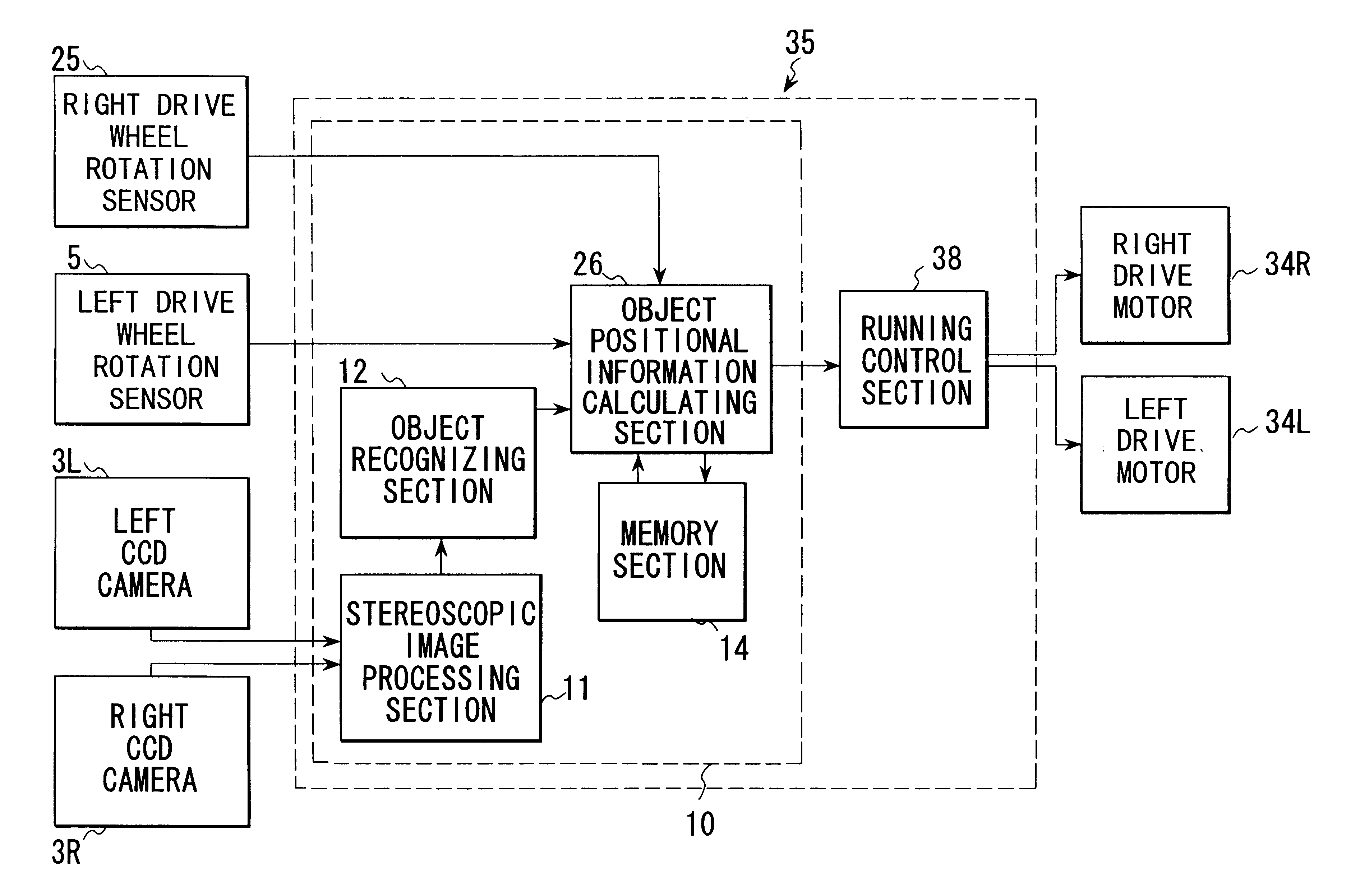
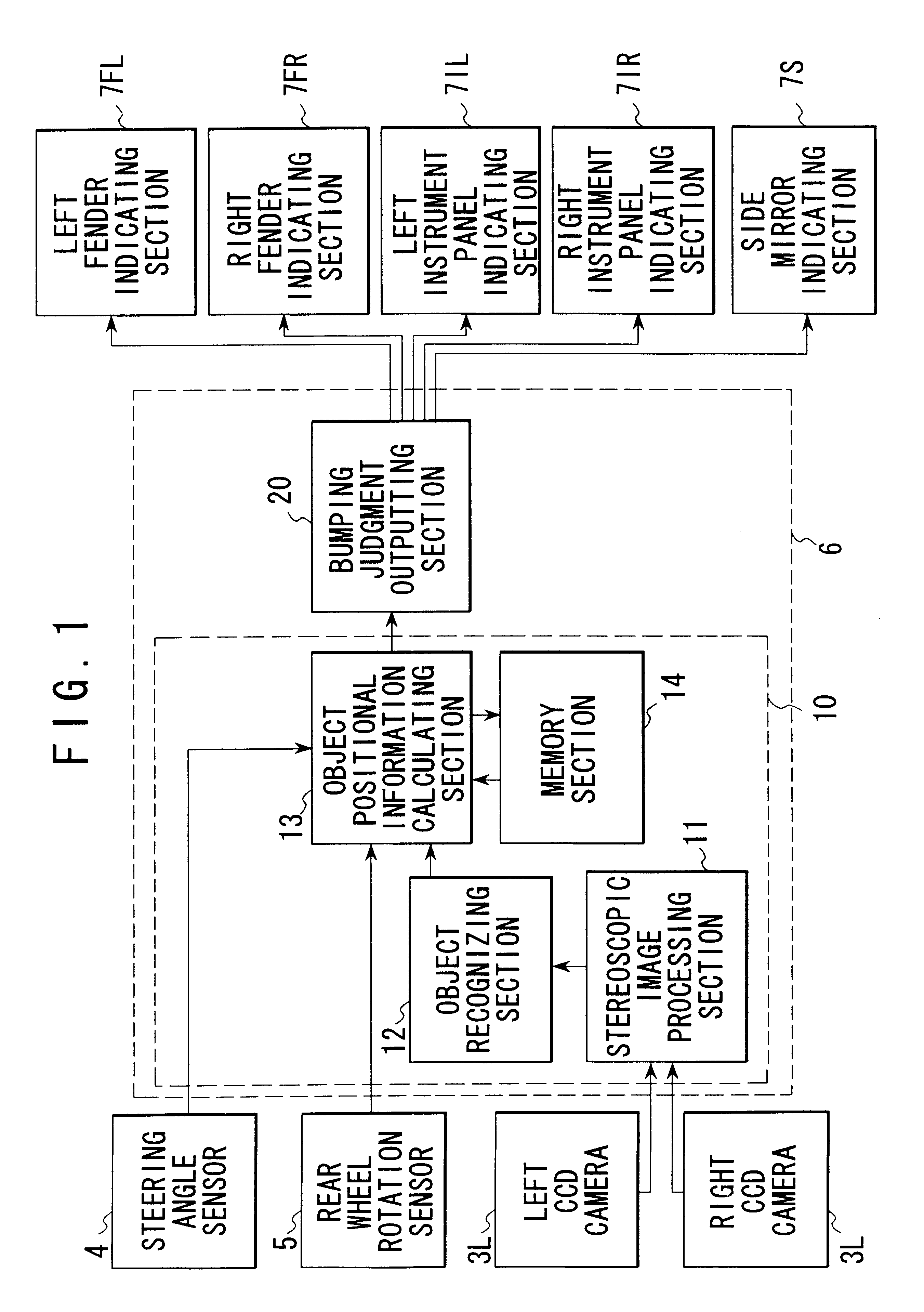
Referring now to FIG. 8 and FIG. 9, the drive assist system 2 comprises a left rear wheel rotation sensor 5, a right rear wheel rotation sensor 25, a left CCD camera, a right CCD camera, a control apparatus 6 and indicating sections 7FL through 7S. The control apparatus 6 further comprises an around-vehicle object recognizing apparatus 10 and a bumping judgment outputting section 20. The around-vehicle object recognizing apparatus 10 further comprises a stereoscopic image processing section 11, an object recognizing section 12, an object positional information calculating section 26 and a memory section 14. The object positional information calculating section 26 calculates and outputs a new object positional information around the vehicle to the bumping judgment outputting section 20 based on the rotation amounts of the left and right rear wheels and the previous object positional information around ...
fourth embodiment
FIG. 17 through FIG. 21 are drawings associated with the present invention. In this embodiment, the CCD camera is rotatably mounted on an autonomous running vehicle 40 so as to take image pictures more broadly. That is to say, as shown in FIG. 17 and FIG. 18, the stereoscopic optical system 3 is fixed on a turn table 41 which is swingable in the horizontal direction so as to obtain a wider range of object information.
The turn table 41 is connected with a motor 42 so as to control the rotation angle thereof. The rotation angle .alpha. (letting the right ahead direction be 0 degrees) is detected by a rotation angle sensor 43 and is inputted to the object recognizing section 48 as shown in FIG. 17. An around-vehicle object recognizing apparatus 47 of the autonomous running control apparatus 45 has the same function as the around-vehicle object recognizing apparatus 10 in the third embodiment except for the object recognizing section 48 in the fourth embodiment.
That is to say, the objec...
PUM
Abstract
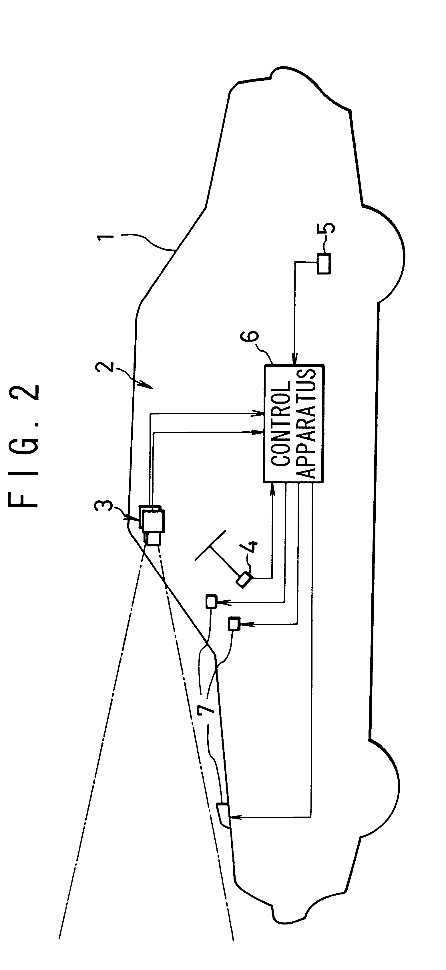
A stereoscopic optical system images a stereoscopic picture image, a stereoscopic image processing section calculates a three-dimensional distance distribution from the stereoscopic picture image, and an object recognizing section recognizes objects from the distance distribution information to calculate a relative position of the objects with respect to the vehicle. On the other hand, a travelling amount of the vehicle is detected by a steering sensor and a rear wheel rotation sensor. Then, an object positional information calculating section calcuLates a new relative position of the objects based on the relative position information memorized in a memory section and the calculated travelling amount of the vehicle and the memory section memorizes the new positional information. And, a bumping judgment outputting section judges the possibility of bumping against the objects based on the new relative position of the objects with reference to memorized information about the external shape of the vehicle. If it is judged therein that there is a possibility of bumping, the bumping judgment outputting section outputs a warning signal to an indicating section.
Description
1. Field of the InventionThe present invention relates to an object recognizing apparatus and method for a vehicle and particularly to an object recognizing apparatus and method to be employed for a drive assist system of an automobile or for an autonomous running control system of an autonomous running vehicle.2. Prior ArtsIn order to compensate an operating sense of a vehicle driver when he passes through narrow roads with frequent obstacles such as walls, poles, guard rails parked vehicles and the like, there has been developed an apparatus for detecting those obstacles by means of tactile sensors such as a corner pole, a contact switch and the like mounted on a vehicle.Further, there has been developed a technique in which ultrasonic sensors are mounted on the side face or corners of the vehicle for measuring a distance to an obstacle and informing a vehicle driver of the measured distance.Further, in recent years, there has been proposed a technology for not only detecting a di...
Claims
Application Information
Patent Timeline
Application Date:The date an application was filed.
Publication Date:The date a patent or application was officially published.
First Publication Date:The earliest publication date of a patent with the same application number.
Issue Date:Publication date of the patent grant document.
PCT Entry Date:The Entry date of PCT National Phase.
Estimated Expiry Date:The statutory expiry date of a patent right according to the Patent Law, and it is the longest term of protection that the patent right can achieve without the termination of the patent right due to other reasons(Term extension factor has been taken into account ).
Invalid Date:Actual expiry date is based on effective date or publication date of legal transaction data of invalid patent.

