I. S. machine

a technology of a spherical mechanism and a spherical tube, which is applied in the direction of glass blowing apparatus, glass shaping apparatus, glass making apparatus, etc., can solve the problems of spherical tube and more difficult problems

Inactive Publication Date: 2001-01-09
EMHART GLASS SA
View PDF6 Cites 5 Cited by
  • Summary
  • Abstract
  • Description
  • Claims
  • Application Information

AI Technical Summary

Benefits of technology

It is accordingly an object of the present invention to provide a plunger mechanism for an I.S. machine wherein the plunger canisters will not be subject to tilting.

Problems solved by technology

As a result, any attempt to change the position of the plungers of the plunger mechanism, by displacing the guide ring, to establish alignment between the plunger of the plunger mechanism and the axis of the mold, will tilt the plunger mechanism relative to the fixed base and this is very undesirable.
This is made even more difficult since all service air lines (as well as all lubrication lines) which connect to the plunger mechanism via individual hoses, must be individually disconnected and reconnected, and, where the configuration of the machine is changed from double gob operation to triple gob operation, for example, new lines have to be defined.
Additionally, since the molds are hung from structure proximate their top, growth due to heat occurs downwardly towards the plunger mechanism and may require repositioning of the neck ring holders and plunger mechanism.

Method used


Image

  • I. S. machine
  • I. S. machine
  • I. S. machine

Examples


Embodiment Construction

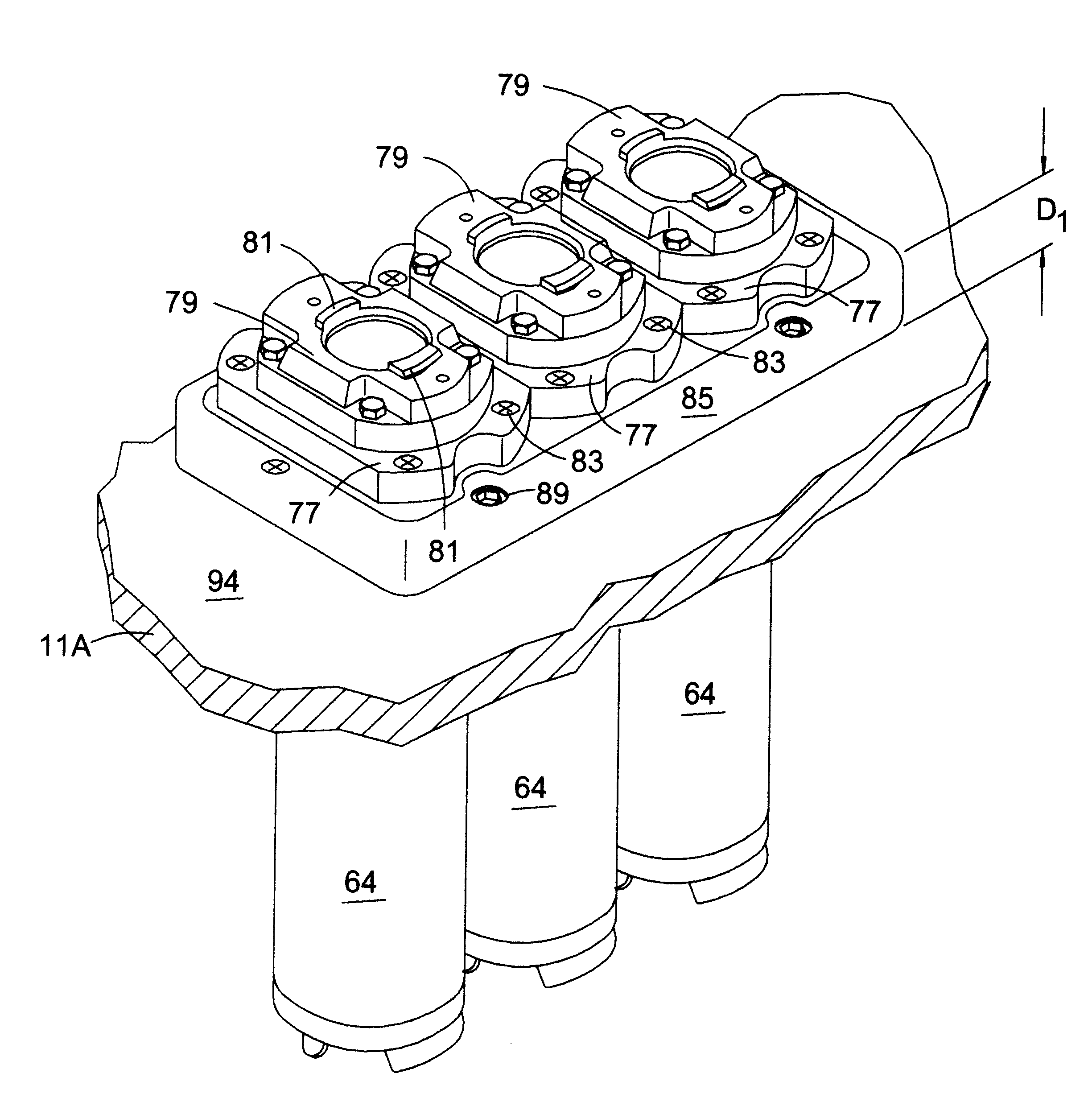
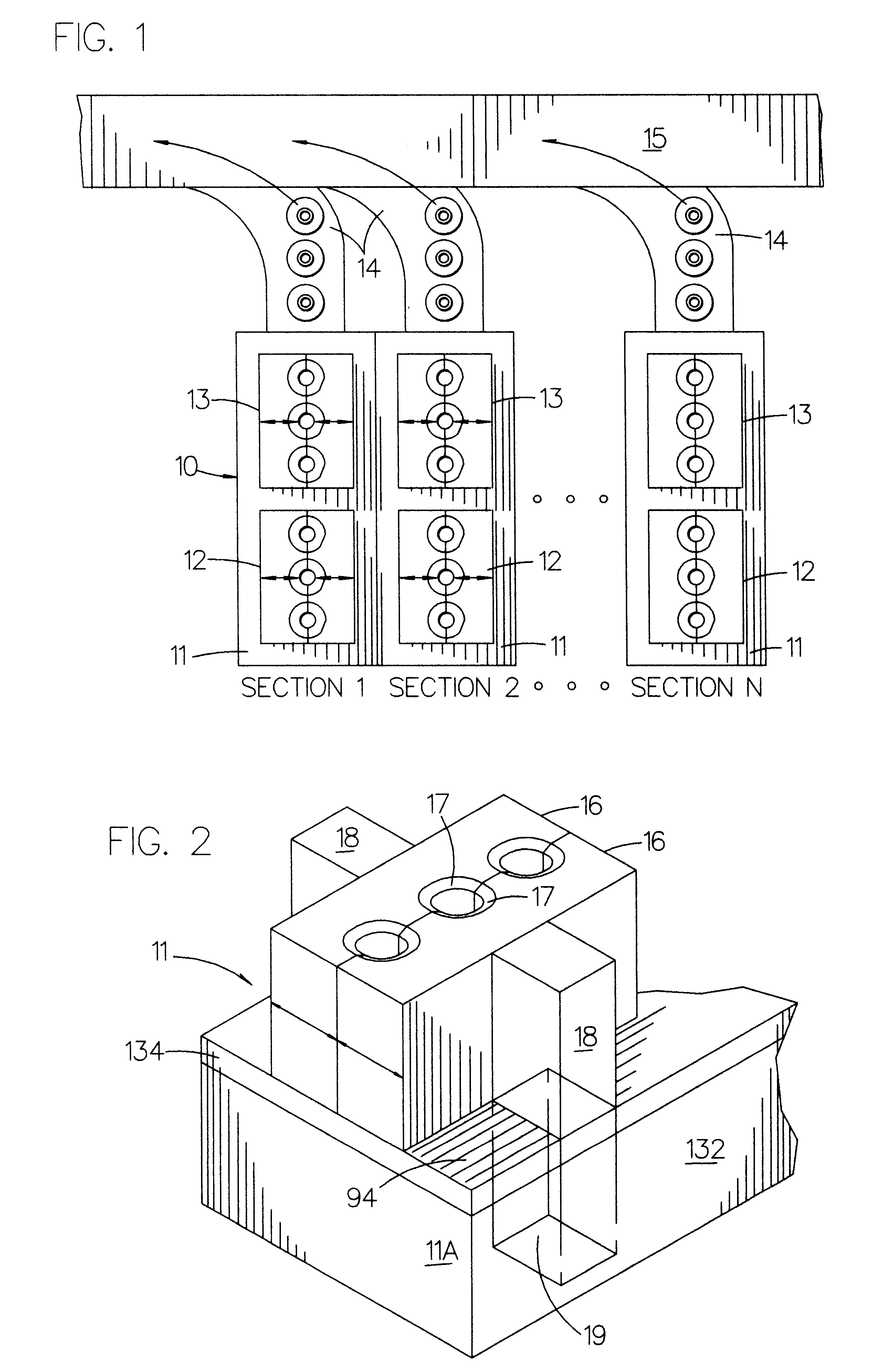
An I.S. machine 10 includes a plurality (usually 6, 8, 10, or 12) of sections 11. A conventional section is made up of a box-like frame or section box 11A (FIG. 2) which houses or supports section mechanisms. Each section has a blank station including a mold opening and closing mechanism 12 carrying blankmolds which receive discrete gobs of molten glass and forms them into parisons and a blow station including a mold opening and closing mechanism 13 carrying blowmolds which receives the parisons and forms the parisons into bottles. One, two, three or four gobs can be processed in each section, each cycle and the machine will be referred to as a single gob, double gob, triple gob (the illustrated embodiment) or quadruple gob machine depending on the number of gobs simultaneously processed in each section during a cycle. The formed bottles are removed from the blow station by a take out mechanism (FIG. 40) and transferred to a dead plate 14 and then transferred by a pusher mechanism (...


PUM

PropertyMeasurementUnit
heightaaaaaaaaaa
lengthaaaaaaaaaa
heightaaaaaaaaaa

Abstract

An I.S. Machine for making glass bottles, having a plurality of sections, each having a blank station for forming a parison. Each section has a section frame having a top surface, and a plunger mechanism including at least one plunger canister having a lower cylinder and an upper flange. A horizontal mounting plate having a top surface and vertical openings for receiving the lower cylinder of each of the plunger canisters is fixedly secured on the top surface of the section frame. The section frame top surface has vertical openings for receiving the lower cylinders of each of the plunger canisters and the flange of the plunger mechanism is secured to the top surface of the mounting plate.

Description

The present invention relates to the plunger mechanism for an I.S. (individual section) machine which transforms gobs of molten glass into bottles in a two step process.The first I.S. machine was patented in U.S. Pat. Nos. 1,843,159, dated Feb. 2, 1932, and 1,911,119, dated May 23, 1933. Today more than 4000 I.S. machines, manufactured by a number of companies, are in use worldwide, producing more than a billion bottles every day of the year. An I.S. (individual section) machine has a plurality of identical sections (a section frame in which and on which are mounted a number of section mechanisms) each of which has a blank station which receives one or more gobs of molten glass and forms them into parisons having a threaded opening at the bottom (the finish) and a blow station which receives the parisons and forms them into bottles standing upright with the finish at the top. An invert and neck ring holder mechanism which includes an opposed pair of arms, rotatable about an invert a...

Claims


Application Information

Patent Timeline
Patent Type & Authority Patents(United States)
IPC IPC(8): C03B9/16C03B9/00
CPCC03B9/16C03B9/3537C03B9/3645
Inventor MANN, PHILIP A.BORBONE, JOSEPH A.STENHOLM, AMEPILSKAER, OVE PERKAMMONEN, JAMOPINKERTON, STEVEN J.
Owner EMHART GLASS SA
Why Eureka
Try Eureka