Inter-tandem pump intake

a technology of intertandem pump and intake pump, which is applied in the direction of fluid removal, earth-moving drilling, borehole/well accessories, etc., can solve the problems of formations that need disposal water, peachy does not teach a method of liquid separation

Inactive Publication Date: 2001-01-16
BAKER HUGHES INC
View PDF17 Cites 31 Cited by
  • Summary
  • Abstract
  • Description
  • Claims
  • Application Information

AI Technical Summary

Benefits of technology

An assembly is provided for use in a well containing a mixture of hydrocarbons and water wherein the assembly utilizes multiple separators to separate hydrocarbons from the mixture. The assembly of the invention injects heavier fluids such as water into the well and pumps lighter fluids such as hydrocarbons to the surface. The assembly includes a first pump section having a production fluid intake for receiving a mixture of oil and water from a production zone and an outlet. The assembly also includes a second pump section having an outlet and an intake that is connected to the outlet of the first pump section. A first separator is pr

Problems solved by technology

Although Peachey teaches the use of multiple separators inside of a separation chamber, Peachy does not teach a method wherein liquids are separated multiple times to

Method used


Image

  • Inter-tandem pump intake
  • Inter-tandem pump intake
  • Inter-tandem pump intake

Examples


Embodiment Construction

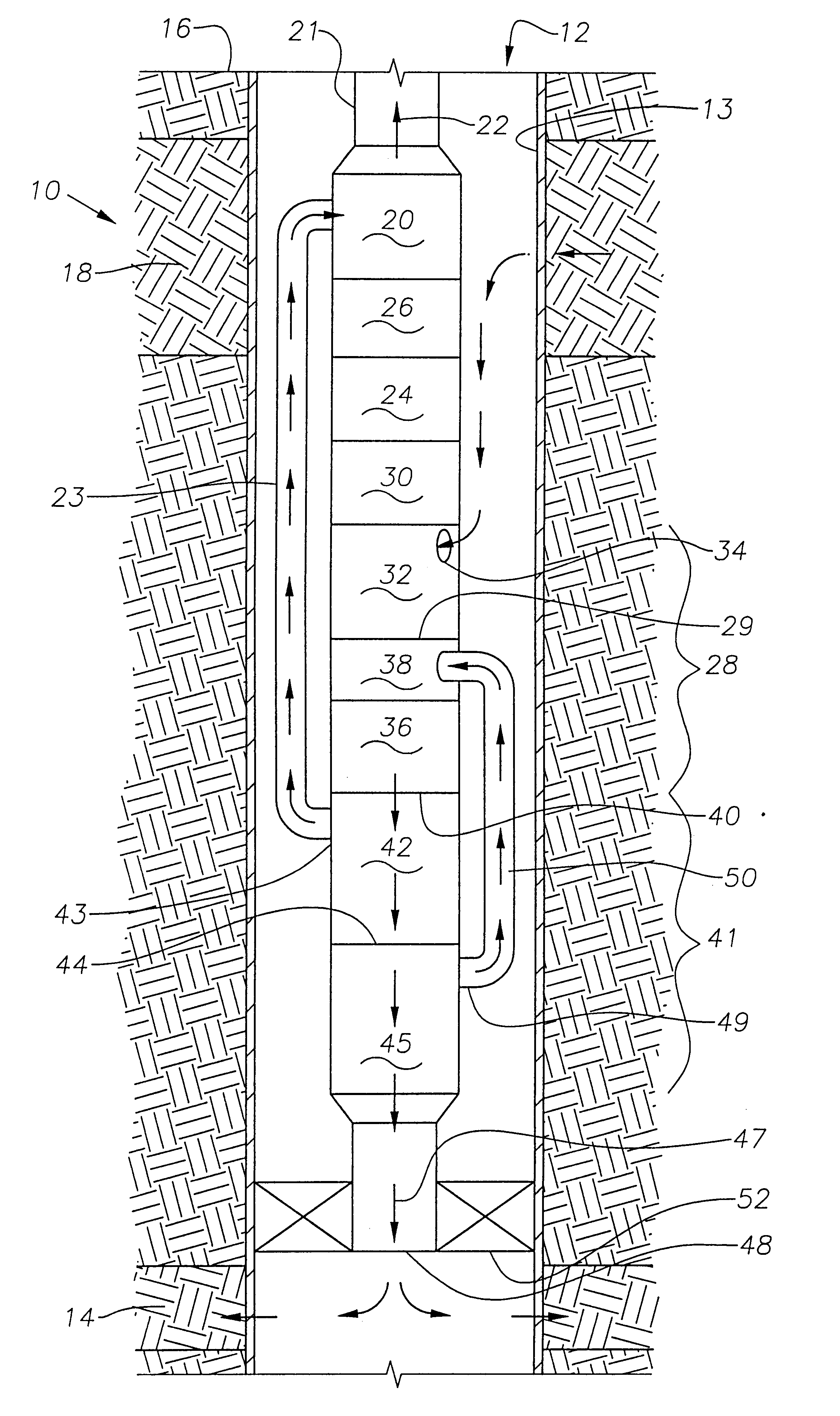
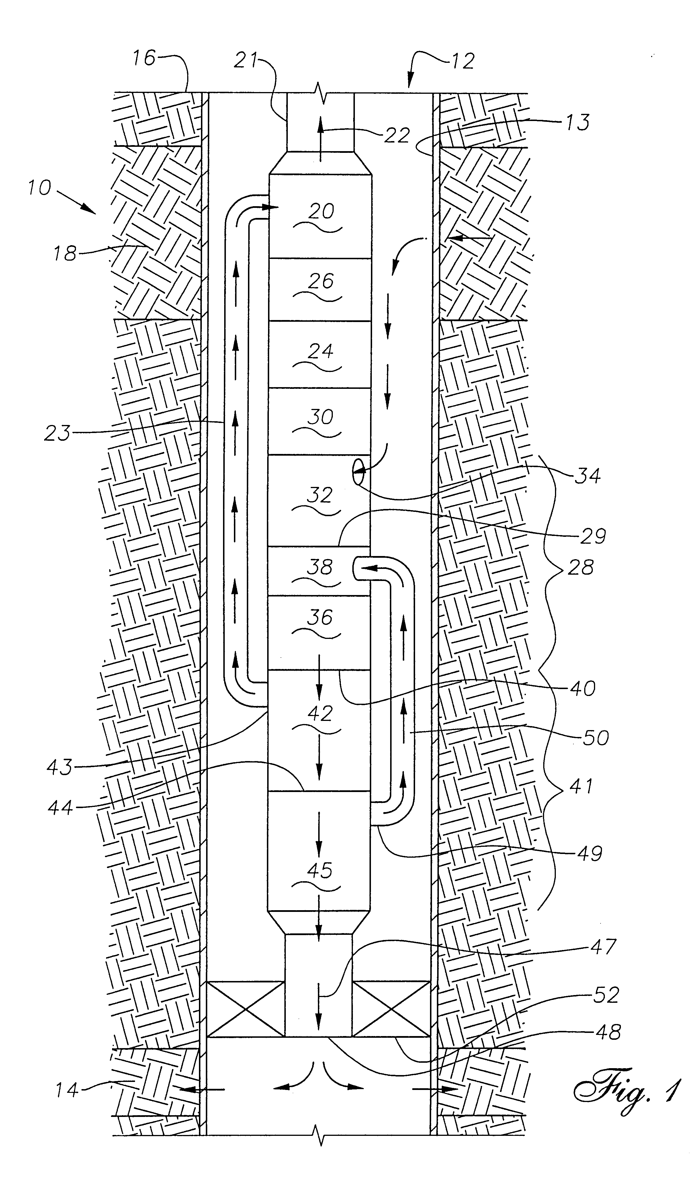
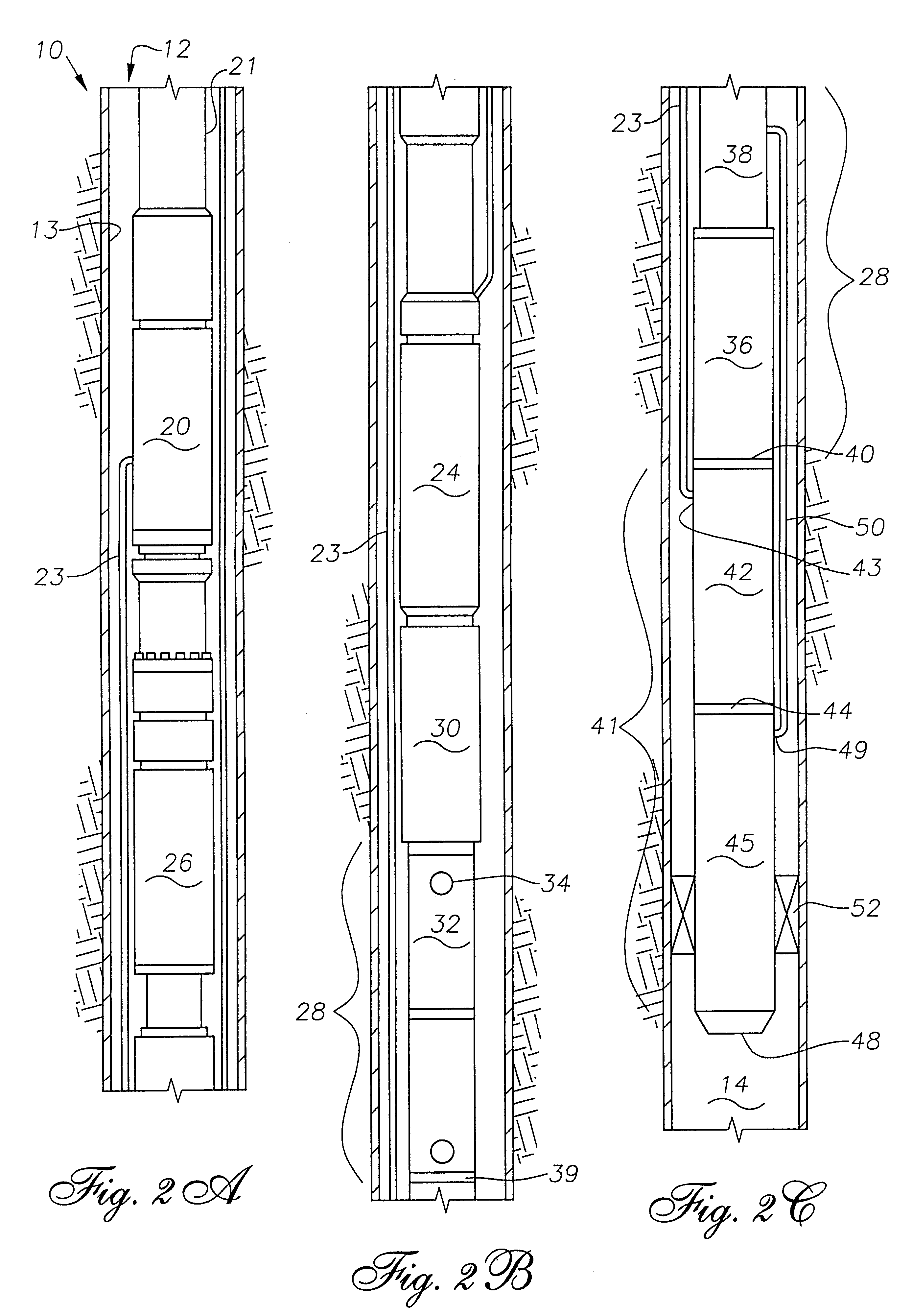
Referring to FIGS. 1 and 2, shown is an assembly designated generally 10, for use in a well 12 containing a mixture of hydrocarbons and water within well casing 13. Assembly 10 is designed to separate hydrocarbons from a mixture of well fluids in well 12. Assembly 10 injects the separated heavier fluids into an injection zone 14 of well 12 and pumps the separated lighter fluids, such as oil, to surface 16. Preferably, assembly 10 is positioned below producing zone 18. The assembly 10 includes an upper pump or third pump section 20 preferably connected to a lower end of production tubing 21 for pumping relatively lighter fluids represented by arrow 22, such as oil, to surface 16. Upper pump 20 is connected to oil bypass tube 23. The upper pump 20 is typically separated from an electrical motor 24 by a seal section 26 as is commonly known in the art.

A tandem pump or lower pump 28 is positioned below upper pump 20 and is preferably separated from motor 24 by seal section 30 which may b...


PUM


Abstract

An assembly for use in a well containing a mixture of hydrocarbons and water wherein the assembly separates hydrocarbons or relatively lighter fluids from the mixture and injects water or relatively heavier fluids into the well. The assembly includes an upper pump that pumps the relatively lighter fluids to the surface. A tandem pump is positioned below the upper pump for pumping well fluids down to a downhole separator. An oil bypass tube is provided in communication with the tandem pump for transferring the relatively lighter fluids to the upper pump, for subsequent pumping to the surface. A recycle tube is also provided that communicates with the downhole separator and the tandem pump for transferring at least a portion of the relatively heavier fluids from the downhole separator to the tandem pump, for pumping the relatively heavier fluids back to the separator.

Description

This invention relates to a submersible pump assembly having a downhole hydrocyclone separator (DHS). In particular, the invention relates to a submersible pump apparatus for use in a well containing a mixture of hydrocarbons wherein the submersible pump assembly pumps lighter fluids or oils to the surface and injects heavier fluids or water into the well.When receiving oil from oil wells containing a mixture of hydrocarbons and water, it is desirable to separate the hydrocarbons from the water and reinject the water either above or below the producing zone. Apparatus and methods have been proposed that make it possible to separate hydrocarbons from water and to reinject the water.U.S. Pat. No. 5,456,837 to Peachey teaches a method of downhole cyclone oil / water separation that utilizes a cyclone separator. The cyclone separator includes a separation chamber, wherein liquids of differing densities are separated. The separator has at least one mixed liquids inlet through which liquids...

Claims


Application Information

Patent Timeline
IPC IPC(8): E21B43/38E21B43/34
CPCE21B43/385
Inventor FOX, MICHAEL JOSEPH
Owner BAKER HUGHES INC
Why Eureka
Try Eureka