Dielectric lens antenna having heating body and radio equipment including the same

a technology of dielectric lens and heating body, which is applied in the direction of instruments, wave based measurement systems, and using reradiation, etc., can solve the problems of deterioration in the efficiency of the dielectric lens antenna 1

Inactive Publication Date: 2001-01-16
MURATA MFG CO LTD
View PDF11 Cites 29 Cited by
  • Summary
  • Abstract
  • Description
  • Claims
  • Application Information

AI Technical Summary

Problems solved by technology

As a result, snow accumulates on a surface of the lens 2 of the motor vehicle when it runs in snow, so that this leads to deterioration in the efficiency of the dielectric lens antenna 1.

Method used


Image

  • Dielectric lens antenna having heating body and radio equipment including the same
  • Dielectric lens antenna having heating body and radio equipment including the same
  • Dielectric lens antenna having heating body and radio equipment including the same

Examples


Embodiment Construction

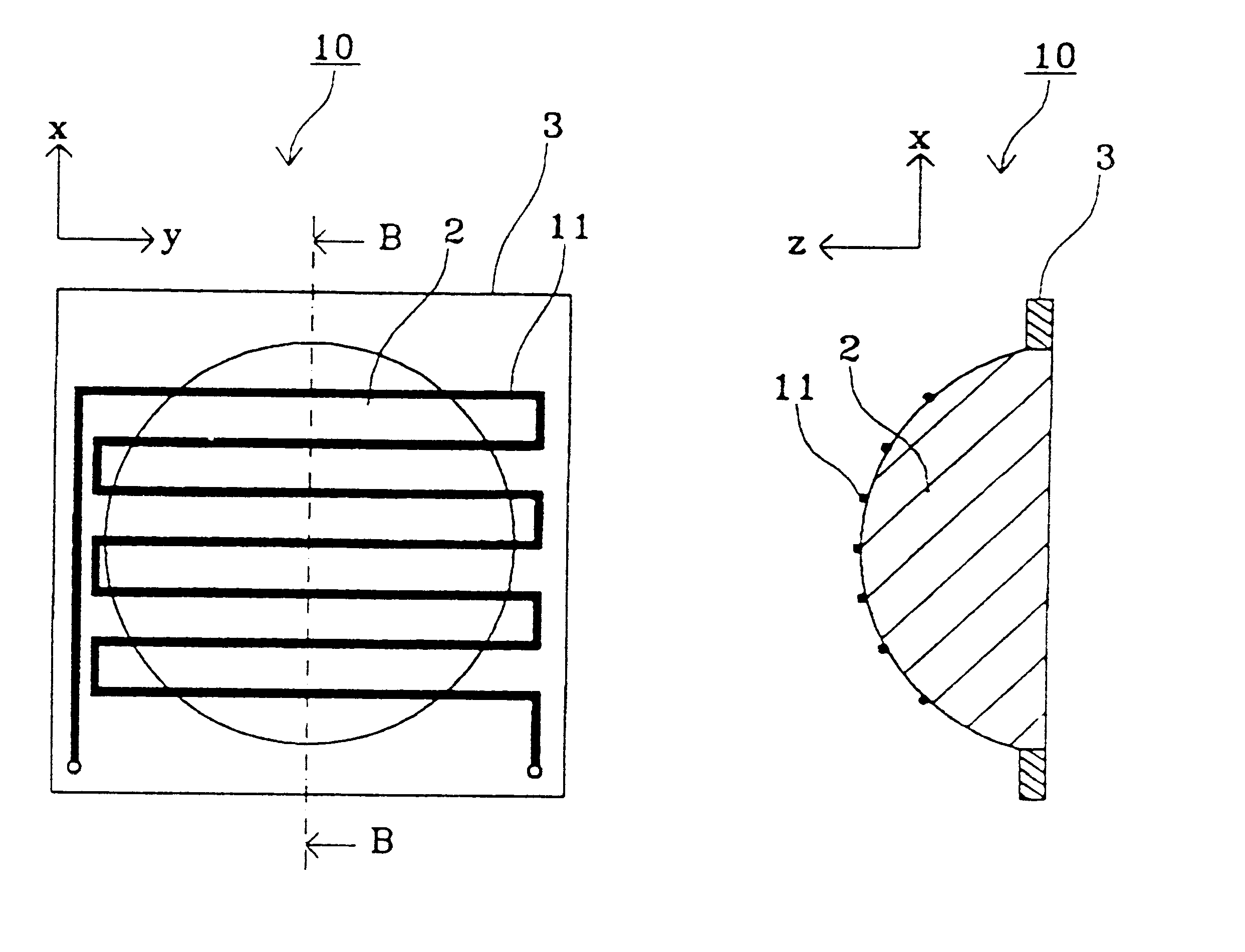
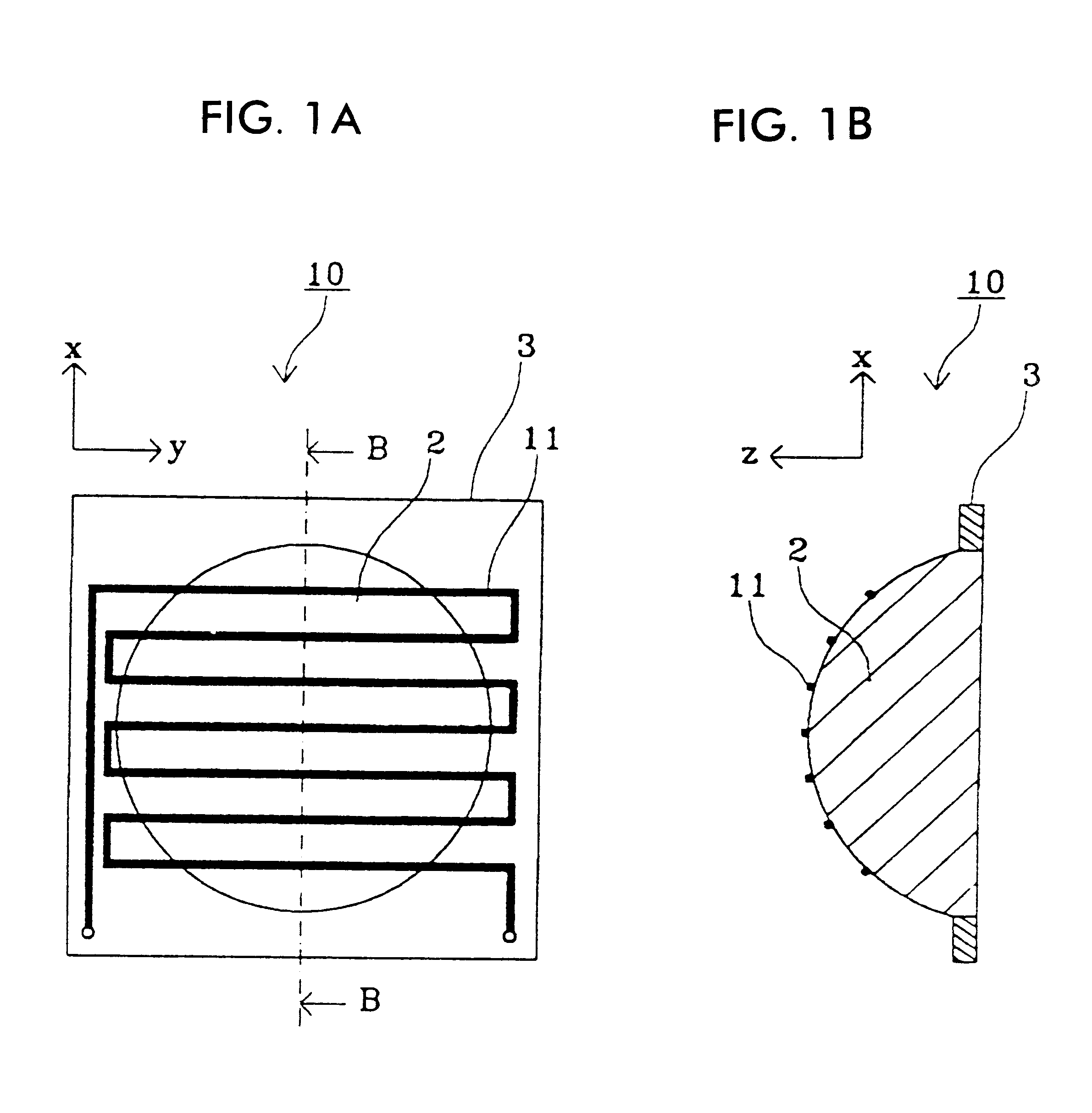
FIG. 1A and FIG. 1B are views of a dielectric lens antenna according to one preferred embodiment of the present invention. In FIG. 1A and FIG. 1B, other components such as a primary radiator are omitted since they are not the principal constituents of the present invention. In the dielectric lens antenna 10 shown in FIGS. 1A and lB, a heating body 11 formed by connecting a plurality of linear heating wires in series is disposed on a surface of a lens 2 whose material is dielectric. Preferably, a metal wire with a large electric resistance, such as a Nichrome wire, is used as each of the heating wires.

In this case, as a method for forming the heating body, when a lens is formed by injection molding, an integrated molding is possible by disposing Nichrome wires in a metal mold. When the lens is ceramic, it is possible to form by printing and baking a pasty heating body on the surface of the lens.

In the dielectric lens antenna 10 formed in such a manner, current is fed to the heating b...


PUM


Abstract

A dielectric lens antenna having a lens comprising a dielectric material and a heating body disposed on a surface of the lens. The dielectric lens antenna has a snow-melting function, which prevents degradation in lens-efficiency.

Description

1. Field of the InventionThe present invention relates to a dielectric lens antenna and radio equipment including the same. More specifically, the present invention relates to a dielectric lens antenna for use in a motor-vehicle-mounted radar, and radio equipment including the same.2. Description of the Related ArtWith the recent development of motor-vehicle-mounted radar, a dielectric lens antenna for use in a motor-vehicle-mounted radar has been required to be resistant to influences due to snowfall and snow accumulation.FIG. 8 shows a conventional dielectric lens antenna. FIG. 8A is a plan view; FIG. 8B is a sectional view taken along the line A--A of FIG. 8A.In FIG. 8, a dielectric lens antenna 1 has such an arrangement that a lens 2, whose material is dielectric, is attached to a frame 3 for retaining it. Other components such as a primary radiator are omitted, since they are not the primary constituents in the present invention.The dielectric lens antenna 1 having such an arra...

Claims


Application Information

Patent Timeline
Patent Type & Authority Patents(United States)
IPC IPC(8): H01Q1/02H01Q15/00H01Q15/08H01Q15/02H01Q1/12H01Q1/42
CPCH01Q1/02H01Q15/08G01S2013/9389G01S2013/93275H01Q1/12H01Q15/02
Inventor ISHIKAWA, YOHEISAKAMOTO, KOICHIYAMADA, HIDEAKINAKAMURA, FUMINORI
Owner MURATA MFG CO LTD
Why Eureka
Try Eureka