Device for mounting a component exposed to a pressurized fluid

a technology of fluidic components and mounting devices, which is applied in the direction of spraying nozzles, medical atomizers, spraying apparatuses, etc., can solve the problems of limited data, large expenditure, and high cost, and achieve the effect of reducing the number of components and reducing the number of parts

Inactive Publication Date: 2001-01-23
BOEHRINGER INGELHEIM INT GMBH
View PDF8 Cites 98 Cited by
  • Summary
  • Abstract
  • Description
  • Claims
  • Application Information

AI Technical Summary

Problems solved by technology

In the case of components made of brittle material, the known methods of mounting the component in pressure tight manner give rise to considerable expenditure and require great care.
Only limited data can reliably be provided as to the service life of a fluidic component mounted in this way.

Method used


Image

  • Device for mounting a component exposed to a pressurized fluid
  • Device for mounting a component exposed to a pressurized fluid
  • Device for mounting a component exposed to a pressurized fluid

Examples


Embodiment Construction

Mounting for a Nebulizer Nozzle of Miniature Construction

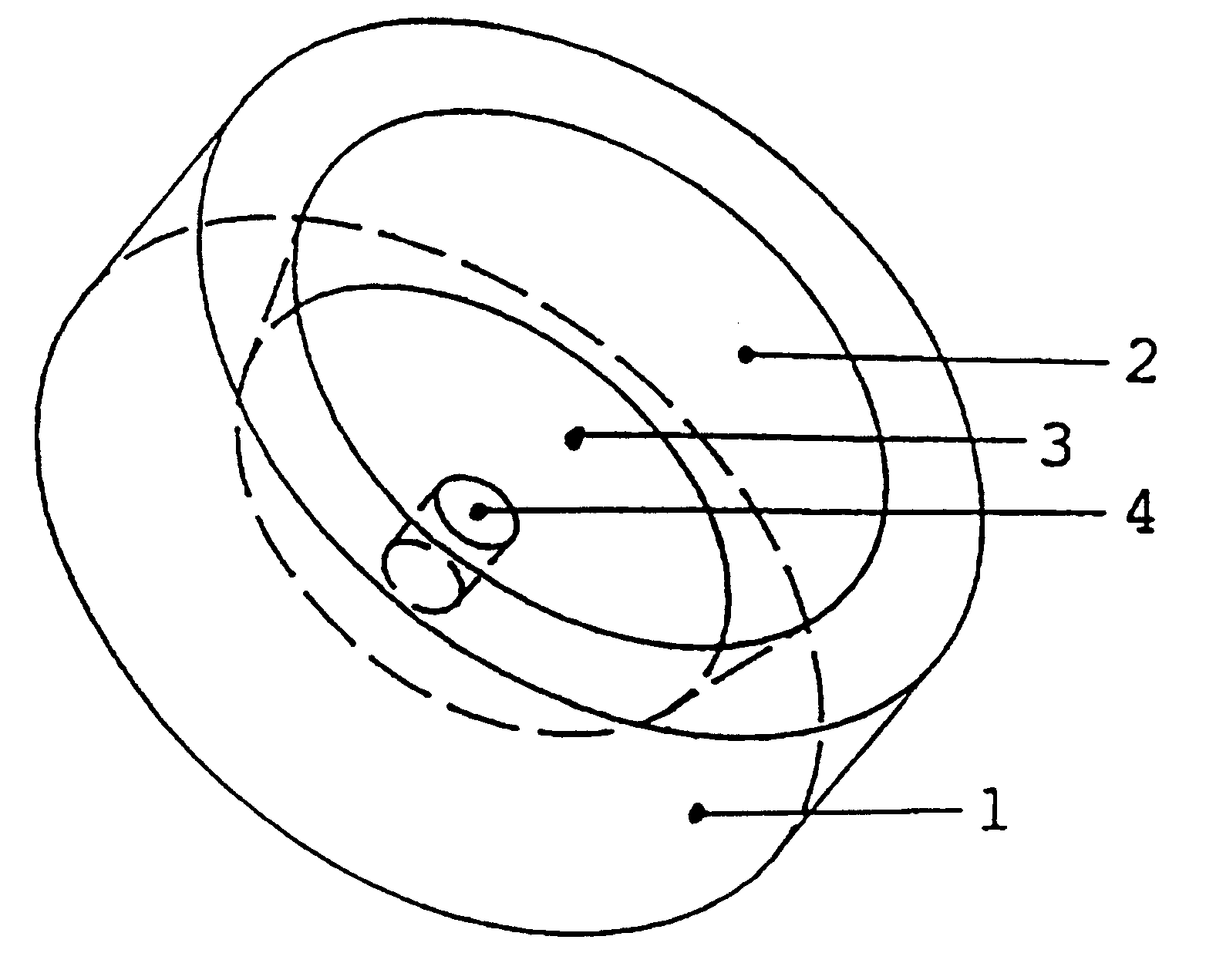
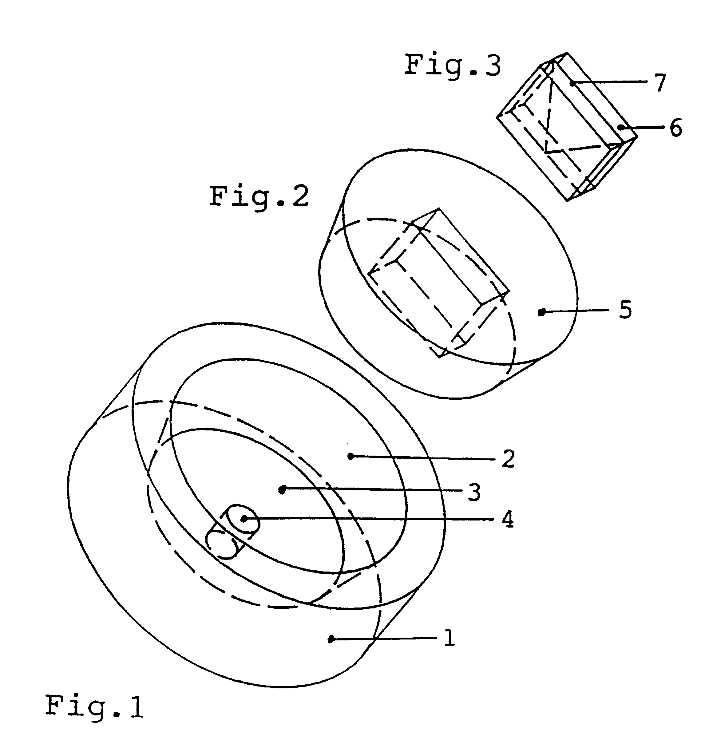
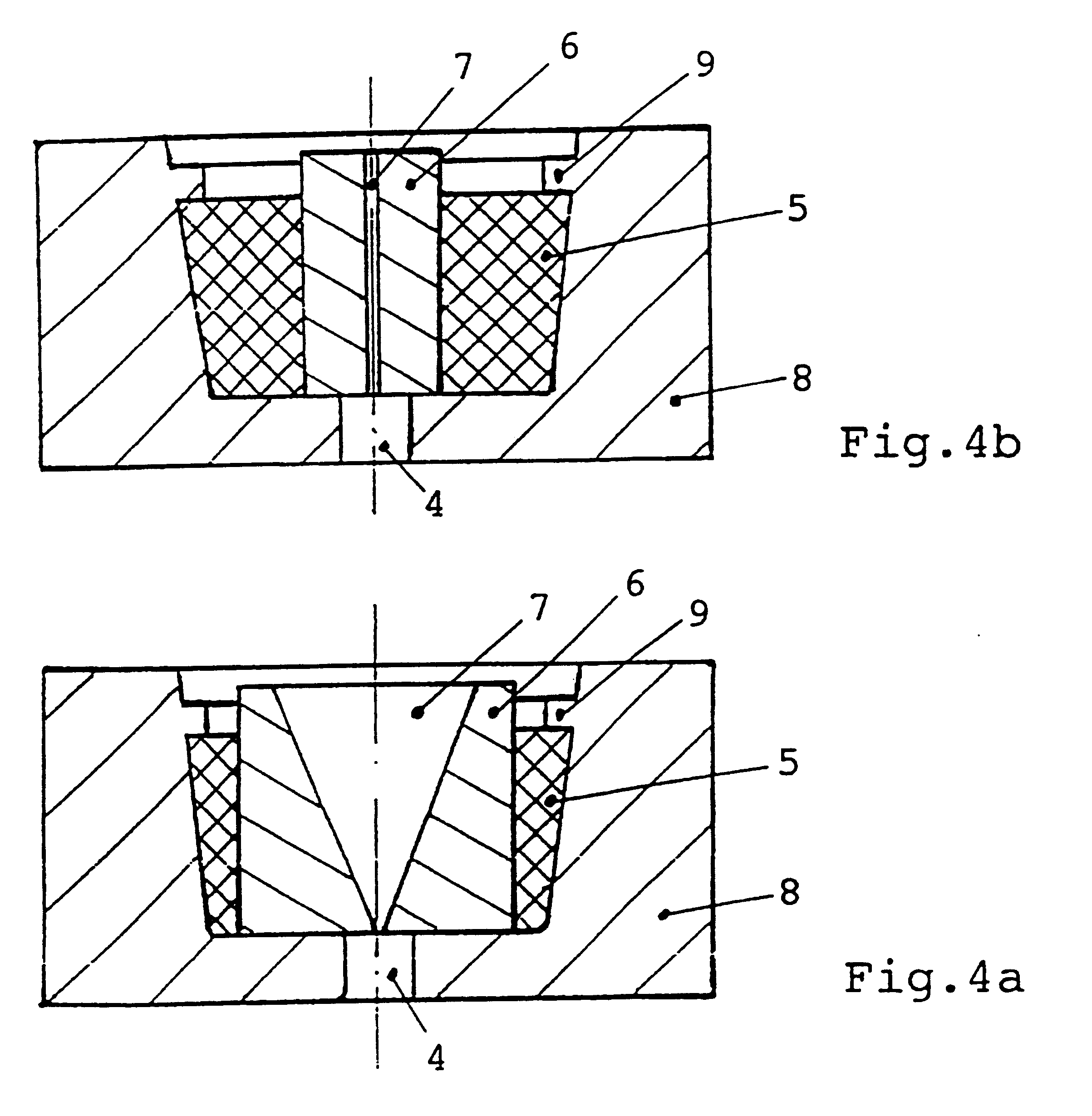
This device consists of a cylindrical holder made of steel with an external diameter of 3.2 mm and a height of 2.6 mm. It contains a recess with an internal diameter of 2.3 mm at the high pressure end and 2.1 mm at the low pressure end. The base of the holder is 0.4 mm thick and contains a bore 0.8 mm in diameter.

The elastomeric shaped component made of silicon rubber is a frustum. Before it is inserted in the holder it has a diameter of 2.3 mm at the high pressure end and 2.2 mm at the low pressure end and is 1.8 mm high. It contains a recess, symmetrical with its axis, extending along its full height, with a width of 1.0 mm and a length of 1.4 mm.

The fluidic component is a box shape made up of two silicon plates, which is 1.1 mm wide, 1.5 mm long and 2.0 mm high. In the contact surface between the plates it contains a flat, triangular recess 400 .mu.m thick, which terminates in a channel 50 .mu.m wide, 50 .mu.m thick and 200...


PUM

PropertyMeasurementUnit
pressureaaaaaaaaaa
sizeaaaaaaaaaa
pressureaaaaaaaaaa

Abstract

The mounting of a component subjected to pressure from a fluid requires special precautions if the component is made of wear resistant, hard and hence generally brittle material and may be destroyed by locally raised stresses. A fluidic component of this kind, made, for example, of silicon/glass is arranged in an elastomeric shaped component, made, for example, of silicon rubber. The inner contours of the elastomeric shaped component correspond to the outer contours of the fluidic component. The outer contours of the shaped component corresponds to the inner contours of a holder. Due to this "floating mounting" there are no unacceptable local pressure peaks and no deformation of the fluidic component. The device is particularly suitable for mounting a fluidic component made of glass or silicon, or miniature dimensions, subject to high pressure.

Description

1. Field of the InventionThe invention relates to a device for holding a fluidic component, particularly nozzles or jets, particularly at high pressures. Holders for microstructured components, particularly microstructured nozzles are of particular interest.The invention relates in particular to a device for holding a microstructured nozzle as used in nebulizers for producing propellant-free medicinal aerosols for inhalation.2. Related ArtNozzles of this kind are disclosed, for example, in WO 94 / 07607. A characteristic feature of these nozzles is that they generate inhalable droplets around 5 .mu.m in size, the liquid which is to be nebulized being sprayed at high pressure (between 50 and 400 bar or more and optionally up to 600 bar) through a nozzle with an opening of less than 10 .mu.m. Nozzles of this kind may be produced, for example, from thin silicon plates and glass plates and have external dimensions in the millimetre range. A typical nozzle consists, for example, of a box s...

Claims


Application Information

Patent Timeline
Patent Type & Authority Patents(United States)
IPC IPC(8): B05B1/00A61M11/00
CPCB05B1/00B05B15/18C08L75/04C08L21/00
Inventor EICHER, JOACHIMGESER, JOHANNES
Owner BOEHRINGER INGELHEIM INT GMBH
Why Eureka
Try Eureka