Coil driving circuit for EAS marker deactivation device

a technology of deactivation device and driving circuit, which is applied in the direction of burglar alarm electric actuation, burglar alarm mechanical actuation, instruments, etc., can solve the problems of deactivation of marker and degaussing of marker bias elemen

Inactive Publication Date: 2001-01-30
SENSORMATIC ELECTRONICS CORP
View PDF5 Cites 35 Cited by
  • Summary
  • Abstract
  • Description
  • Claims
  • Application Information

AI Technical Summary

Benefits of technology

It is an object of the present invention to provide an energizing circuit for an EAS marker deactivation device wherein the circuit operates without user input and is not dependent upon marker detection for reliable operation.
It is a further object of the invention to provide an energizing circuit which makes the deactivation device convenient to use.

Problems solved by technology

A magnetomechanical marker swept over the top of the device is exposed to a decaying-amplitude alternating field as the marker exits the region above the deactivation device, resulting in degaussing of the marker bias element and deactivation of the marker.

Method used


Image

  • Coil driving circuit for EAS marker deactivation device
  • Coil driving circuit for EAS marker deactivation device
  • Coil driving circuit for EAS marker deactivation device

Examples


Embodiment Construction

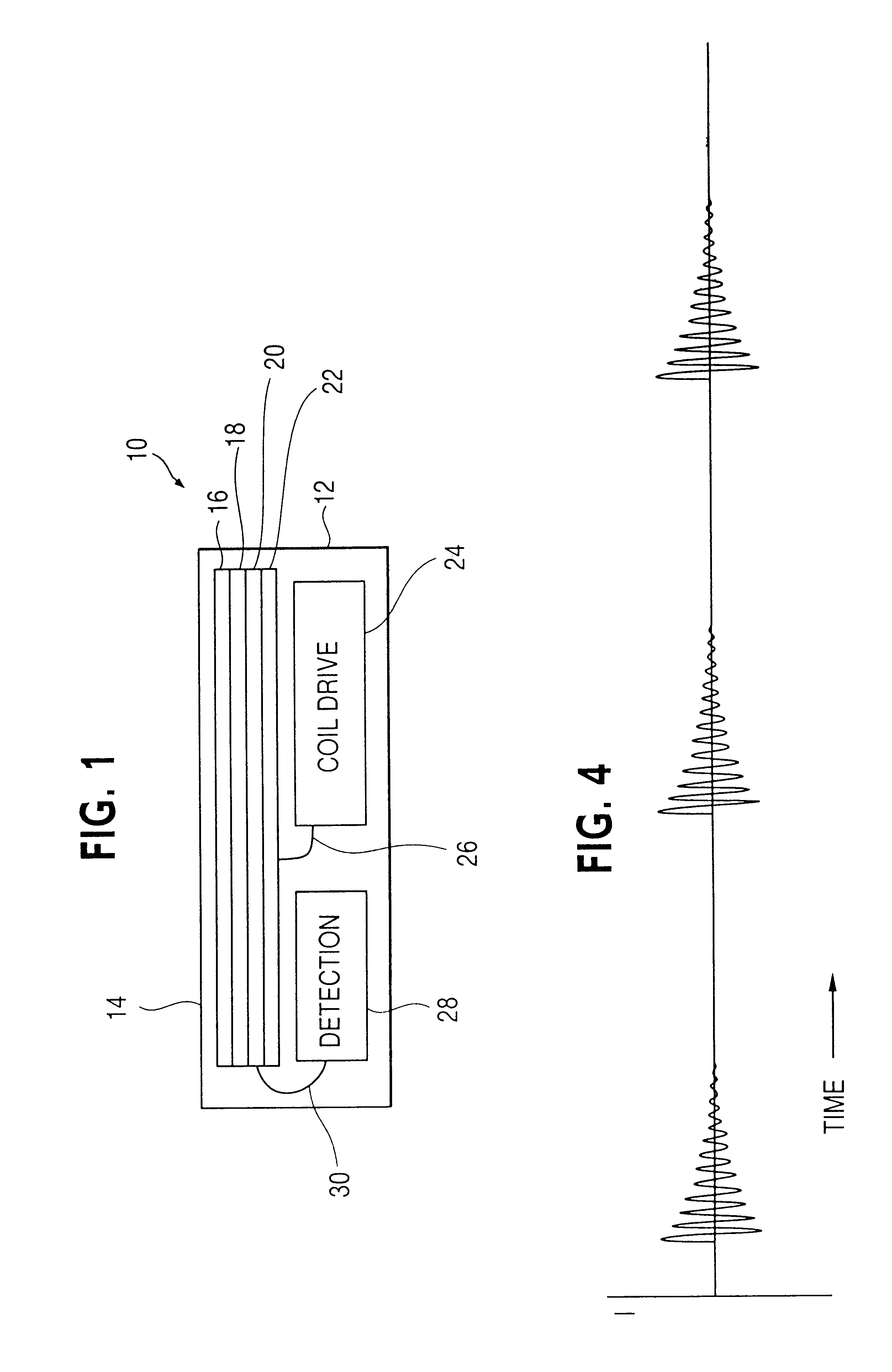
A preferred embodiment of the invention will now be described, initially with reference to FIG. 1.

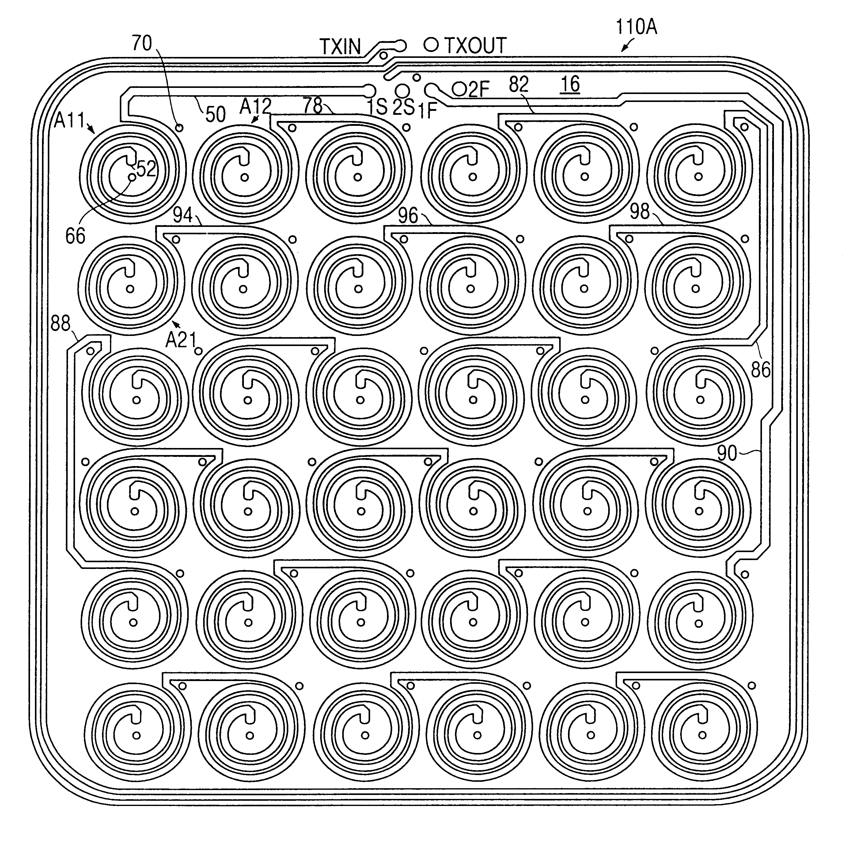
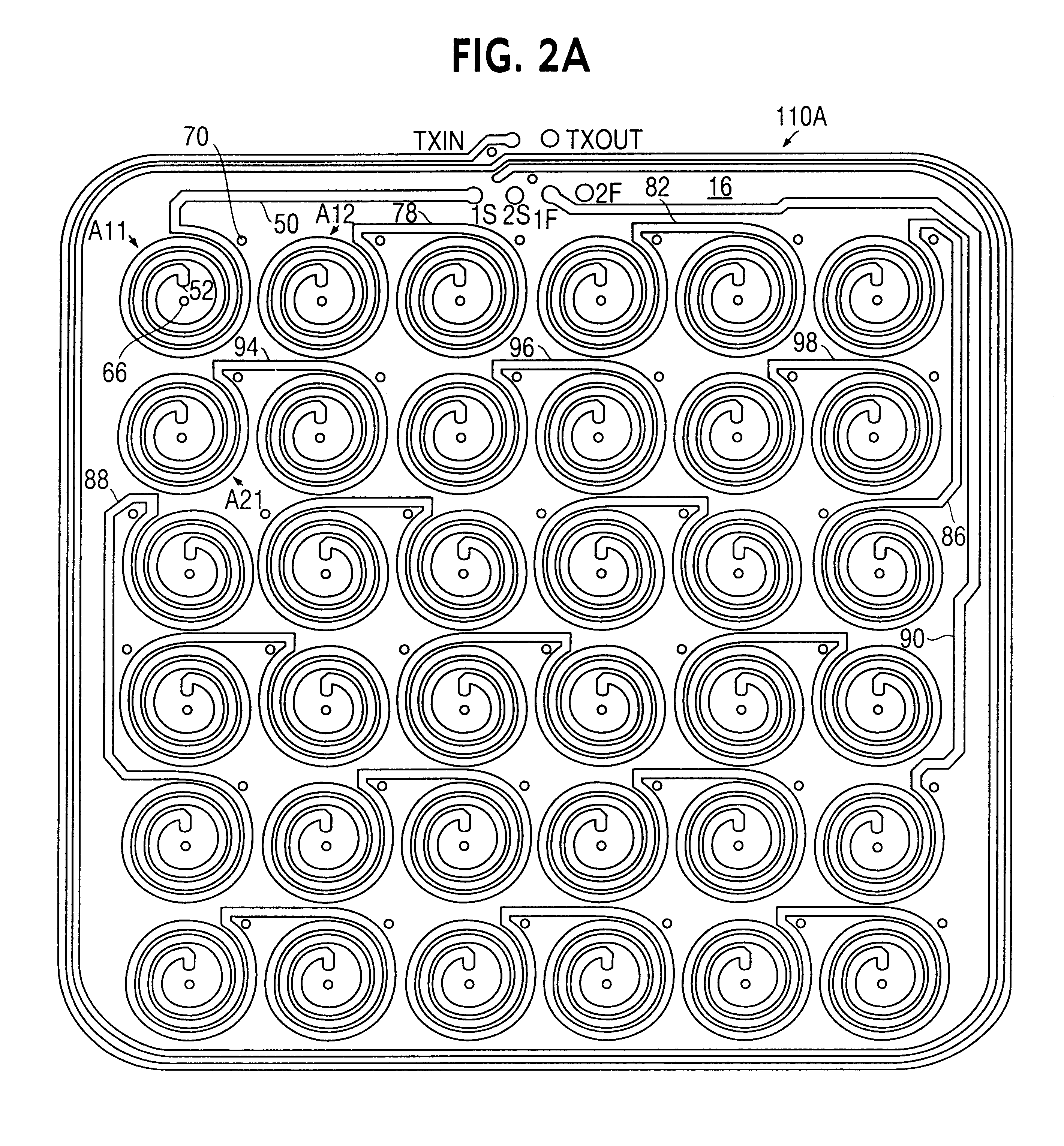
FIG. 1 is a schematic vertical sectional view of a marker deactivation device 10 provided in accordance with the invention. The deactivation device 10 includes a housing 12 which may be formed, in accordance with conventional practice, of molded plastic, and includes a substantially flat, planar top surface 14 at which EAS markers are presented for deactivation. Positioned within the housing 12 just below the top surface 14 is a vertically stacked arrangement of substrates 16, 18, 20, 22. As will be seen, each of the substrates has formed thereon a coil array, the respective coil arrays being interconnected to form a composite coil array which is driven to generate a deactivation magnetic field at, and for some distance above, the top surface 14.

Also contained within the housing 12 is a coil driving circuit 24 which is connected via cable 26 to the aforementioned composite coil array, w...


PUM


Abstract

A device for deactivating a magnetomechanical electronic article surveillance (EAS) marker includes a deactivation coil array and a coil driving circuit. The coil driving circuit repetitively energizes the deactivation coil array according to a predetermined timing to generate a magnetic field for deactivating the EAS marker. The driving circuit includes at least one storage capacitor, circuitry for charging the at least one storage capacitor and a switching circuit for selectively forming a resonant circuit which includes the storage capacitor and at least some of the coils of the coil array to generate a ring-down signal in the coils. A timing circuit controls the switching circuit to generate the ring-down signal repetitively at the predetermined timing.

Description

This invention relates generally to electronic article surveillance (EAS) and pertains more particularly to so-called "deactivators" for rendering EAS markers inactive.It has been customary in the electronic article surveillance industry to apply EAS markers to articles of merchandise. Detection equipment is positioned at store exits to detect attempts to remove active markers from the store premises, and to generate an alarm in such cases. When a customer presents an article for payment at a checkout counter, a checkout clerk either removes the marker from the article, or deactivates the marker by using a deactivation device provided to deactivate the marker.Known deactivation devices include one or more coils that are energizable to generate a magnetic field of sufficient amplitude to render the marker inactive. One well known type of marker (disclosed in U.S. Pat. No. 4,510,489) is known as a "magnetomechanical" marker. Magnetomechanical markers include an active element and a bi...

Claims


Application Information

Patent Timeline
Patent Type & Authority Patents(United States)
IPC IPC(8): G08B13/24
CPCG08B13/2411
Inventor MAITIN, STEVEN R.EASTER, RONALD B.
Owner SENSORMATIC ELECTRONICS CORP
Why Eureka
Try Eureka