
Method of detecting overcoating rubber flowed in space between core member and securing metal fitting of polymer insulator

a technology of polymer insulator and overcoating rubber, which is applied in the direction of material strength using steady torsional force, material analysis, instruments, etc., can solve the problems of inability to detect overcoating rubber in the space by using x-ray, ultrasonic flaw detection method, and the method of using acoustic emission

Inactive Publication Date: 2001-02-20
NGK INSULATORS LTD
View PDF4 Cites 5 Cited by
  • Summary
  • Abstract
  • Description
  • Claims
  • Application Information

AI Technical Summary

Benefits of technology

In the present invention, a torque is applied in a circumferential direction to the securing metal fitting, after forming the overcoating rubber but before fixing to the securing metal fitting to the core member. Therefore, the index provided on a surface of the overcoating, which is preferably the parting line generated on a surface of the overcoating during forming, is deformed, and thus it is possible to detect whether the overcoating rubber is existent or not in the space between the securing metal member and the core member in response to the deforming extent indicated by the index. In this detection method mentioned above, since it is not necessary to use so much equipment for detection and it is performed in an easy manner, it is possible to perform the detection of whether or not the overcoating is existent in the space between the core member and the securing metal fitting easily even in a manufacturing field.
Moreover, in a preferred embodiment if torques rotating in a reverse direction with each other are applied to the securing metal fittings, which are arranged at both ends of the core member, it is possible to detect the overcoating rubber simultaneously at both ends. Preferably, if the deforming extent indicated by the index is measured by detecting a deforming amount in a circumferential direction between two points on the parting line with a predetermined distance, one of which is preferably set at a position at which the parting line and the securing metal fitting are contacted, and defining the detected deforming amount between two points as the deforming extent indicated by the index, it is possible to measure the deforming extent correctly.

Problems solved by technology

However, if the overcoating rubber should flow into the space between the core member and the securing metal fitting, the tensile strength of the polymer insulator is decreased.
However, in the case of detecting whether or not the overcoating rubber which is flowed into the space between the core member and the securing metal fitting, as existent, it is not possible to detect the overcoating rubber in the space by the method of using X-ray, the ultrasonic flaw detection method and the method of using acoustic emission.

Method used


Image

  • Method of detecting overcoating rubber flowed in space between core member and securing metal fitting of polymer insulator
  • Method of detecting overcoating rubber flowed in space between core member and securing metal fitting of polymer insulator
  • Method of detecting overcoating rubber flowed in space between core member and securing metal fitting of polymer insulator

Examples


experiment 1

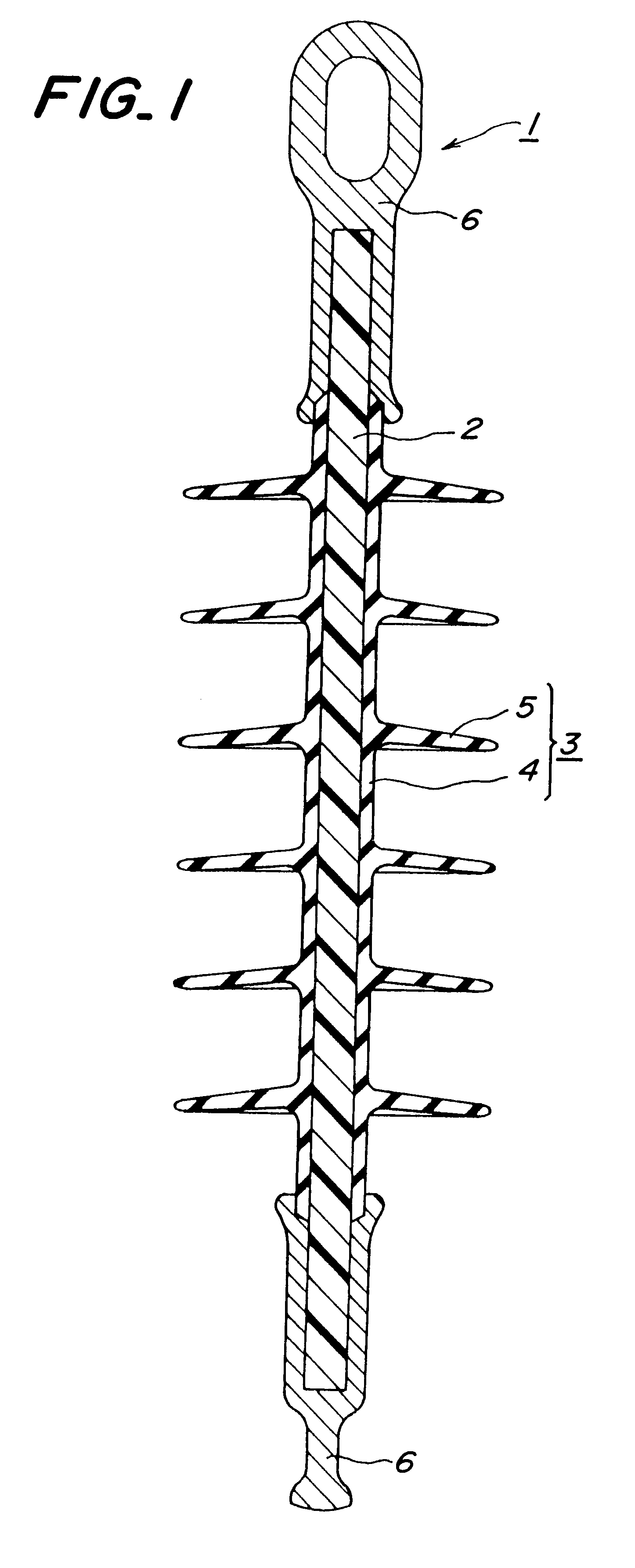
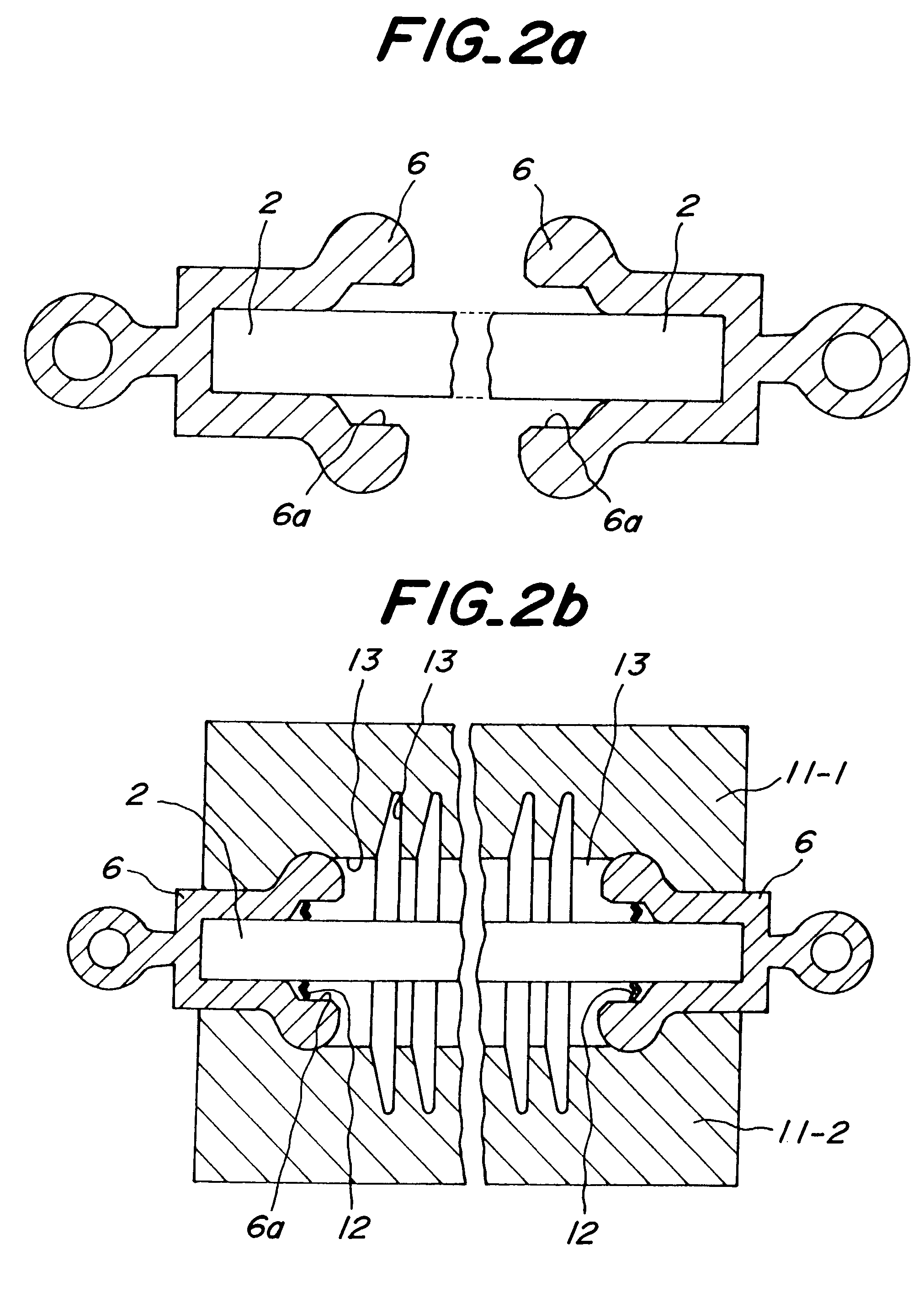
At first, it was examined whether or not the deformation of the cured connection portion between the securing metal fitting 6 and the overcoating 3 by applying a torque to the securing metal fitting 6 was affected for seal performance at the cured connection portion mentioned above in the polymer insulator. This is a preamble for performing the method of detecting the overcoating rubber flowed in the space between the core member and the securing metal fitting of the polymer insulator according to the invention. The polymer insulator, in which the overcoating rubber 7 is formed but the securing metal fitting 6 is not clamped, was manufactured according to the manufacturing method mentioned above. Then, torques of 1.0 kg.multidot.fm rotating in a reverse direction with each other were applied respectively to the securing metal fittings 6 arranged at both ends of the thus prepared polymer insulator 1, in order to simulate operations of the detection method according to the invention. ...

experiment 2

Next, an example of the invention and a comparative example were prepared. In the example of the invention, the overcoating rubber 7 was not flowed into the space between the securing metal fitting 6 and the FRP core 2 during forming. In the comparative example, the overcoating rubber 7 was flowed into the space between the securing metal fitting 6 and the FRP core 2 furring forming. Both in the example of the invention and the comparative example, the deformation extent was measured when a torque applied to the securing metal fitting 6 was varied. The deformation extent was measured from the deformation amount b between two points where the distance a was set to 20 mm in FIG. 3. The result is shown in FIG. 5. In FIG. 5, the example of the invention is largely different from the comparative example on the deformation amount. Therefore, it was confirmed that it is possible to detect whether or not the overcoating rubber is existent in the space between the securing metal fitting and ...


PUM


Abstract

A method of detecting an overcoating rubber flowed in a space between a core member and a securing metal fitting of a polymer insulator having the core member, the overcoating arranged around the core member and the securing metal fitting fixed to at least one end of the core member, is disclosed. The method includes the steps of: applying a torque in a circumferential direction to the securing metal fitting, after forming the overcoating rubber but before fixing the securing metal fitting to the core member; deforming an index provided on a surface of the overcoating; and detecting whether the overcoating rubber is existent or not in the space between the securing metal member and the core member in response to a deforming extent indicated by the index.

Description

1. Field of the InventionThe present invention relates to a method of detecting an overcoating rubber flowed in a space between a core member and a securing metal fitting of a polymer insulator having the core member, the overcoating arranged around the core member and the securing metal fitting fixed to at least one end of the core member.2. Description of the Related ArtGenerally, there is known a polymer insulator comprising a core member, overcoating arranged around the core member, and securing metal fitting fixed to at least one end of the core member. In order to keep a seal performance between the securing metal fitting and the overcoating, when such a polymer insulator is manufactured, the applicant proposed, in Japanese Patent Application No. 9-56297, a method of manufacturing the polymer insulator, in which an overcoating rubber for forming the overcoating is formed under a condition such that the securing metal fitting is set to the core member without being fixed, the s...

Claims


Application Information

Patent Timeline
IPC IPC(8): H01B17/00H01B19/00H01B17/32
CPCH01B17/325H01B19/00
Inventor TANI, TAKAOSUZUKI, TOMIO
Owner NGK INSULATORS LTD
Learn More