

Video signal processing apparatus
a video signal and processing apparatus technology, applied in the direction of color television details, television systems, conversion with cinematograph film standards, etc., can solve the problem that the effect of pulling down information cannot be effectively used
- Summary
- Abstract
- Description
- Claims
- Application Information
AI Technical Summary
Benefits of technology
Problems solved by technology
Method used
Image

Examples
first embodiment
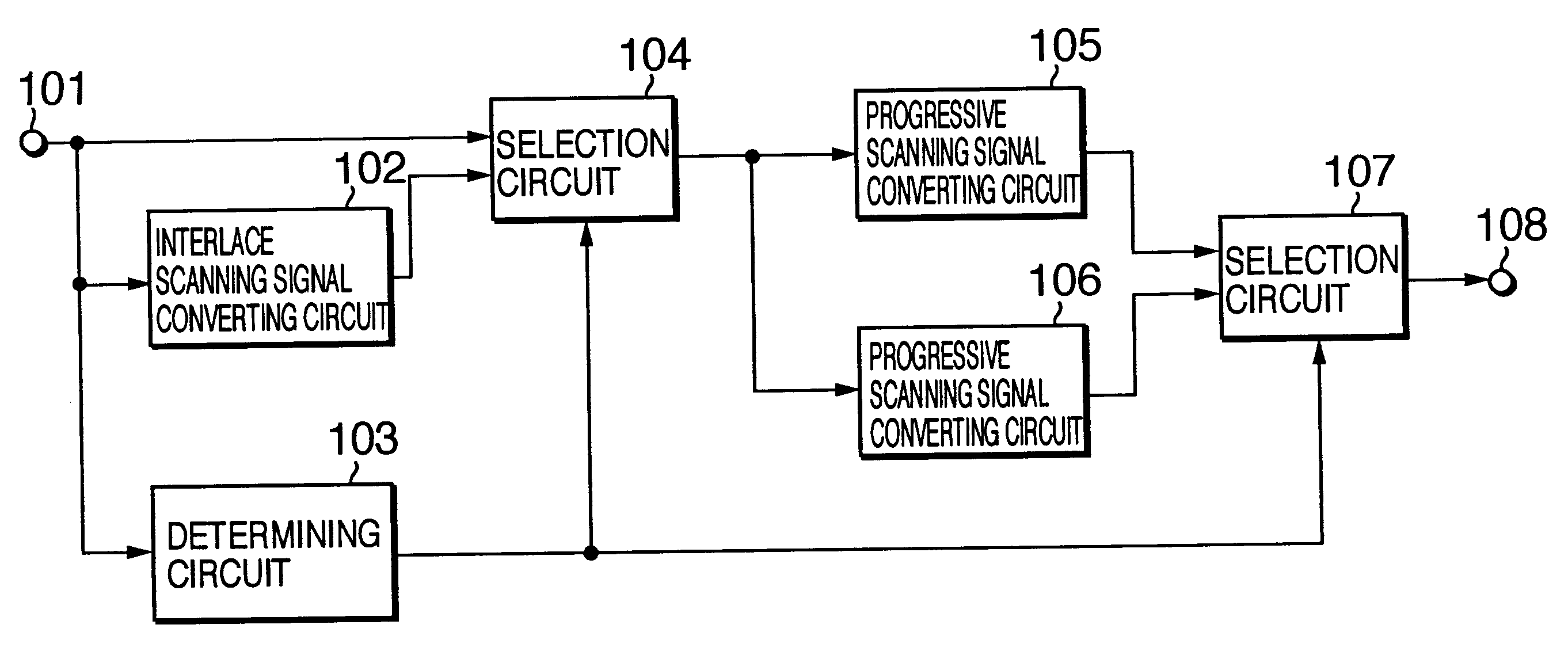
Next, with reference to the accompanying drawings, embodiments of the present invention will be described. FIG. 1 is a block diagram showing the structure of a video signal processing apparatus according to the present invention. In FIG. 1, a 24 fps progressive scanning video signal or a conventional NTSC format interlace scanning video signal is input from an input terminal 101. The input video signal is supplied to one input terminal of a selection circuit 104, an interlace scanning signal converting circuit 102, and a determining circuit 103.
The determining circuit 103 determines whether the input video signal is a 24 fps progressive scanning video signal or a conventional NTSC format interlace scanning video signal and outputs a determination signal corresponding to the determined result. The interlace scanning signal converting circuit 102 converts a 24 fps progressive scanning video signal into a conventional NTSC format interlace scanning video signal with 3-2 pulldown format...
second embodiment
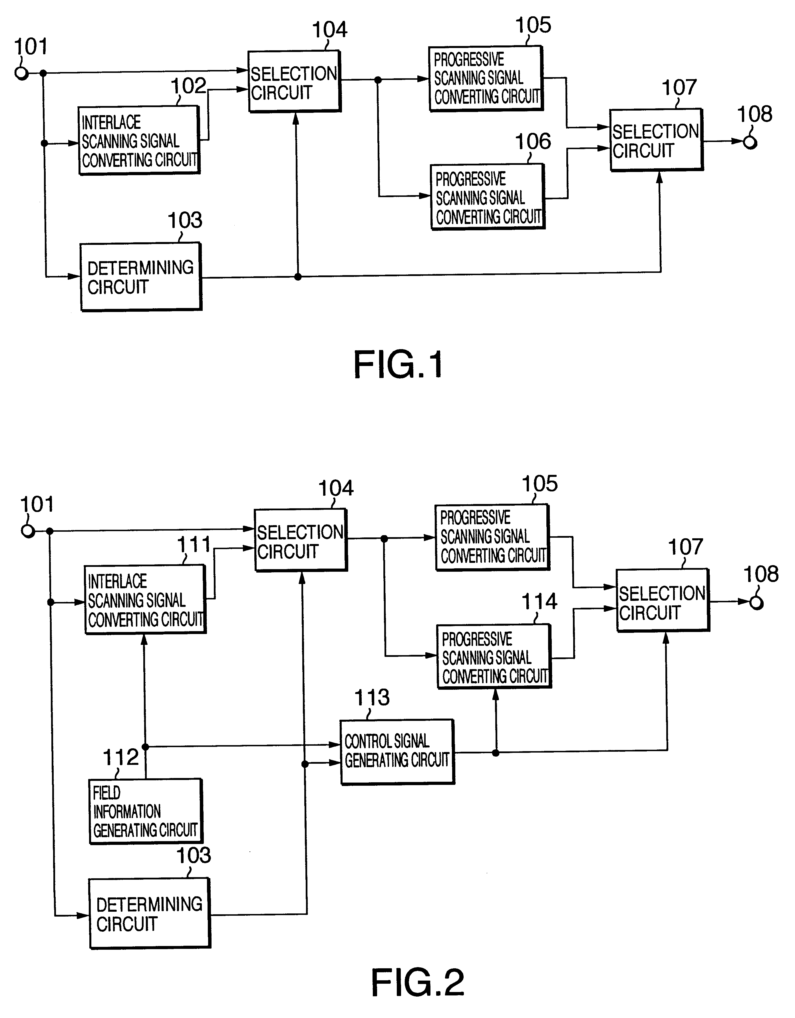
FIG. 2 is a block diagram showing the structure of a video signal converting apparatus according to the present invention. For simplicity, in FIG. 2, similar portions to those in FIG. 1 are denoted by similar reference numerals.
A video signal that is input from an input terminal 101 is supplied to an input terminal 104a of a selection circuit 104, a determining circuit 103, and an interlace scanning signal converting circuit 111.
As with the interlace scanning signal converting circuit 102 shown in FIG. 1, the interlace scanning signal converting circuit 111 converts a 24 fps progressive scanning signal into a conventional NTSC format interlace scanning video signal with the 3-2 pulldown format. Then, field information that represents which field is generated with which frame is obtained from a field information generating circuit 112. In other words, by means of the field information received from the field information generating circuit 112, the interlace scanning signal converting...
third embodiment
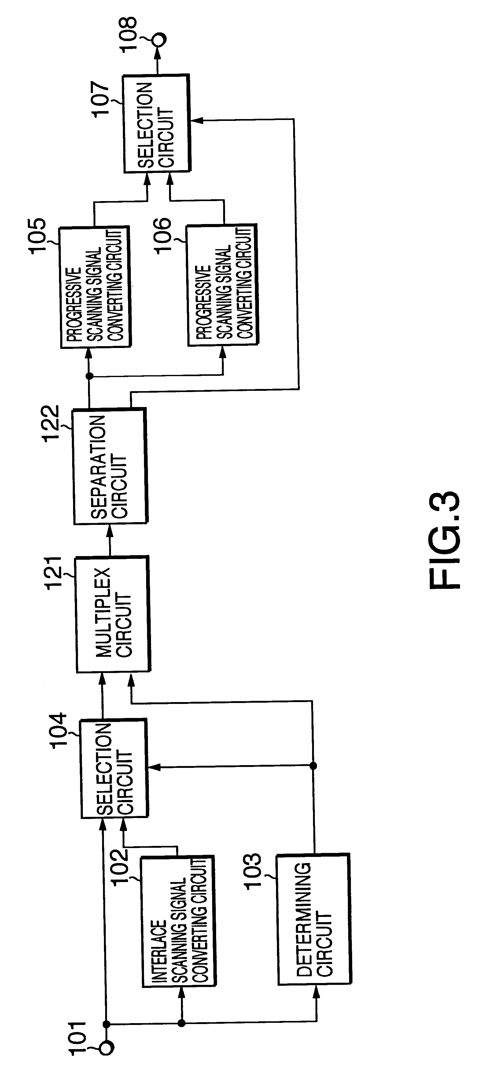
FIG. 3 is a block diagram showing the structure of a video signal processing apparatus according to the present invention. For simplicity, in FIG. 3, similar portions to those in FIG. 1 are denoted by similar reference numerals. In the following, different structural portions will be described.
In FIG. 3, a video signal received from a selection circuit 104 and a determination signal received from a determining circuit 103 are supplied to a multiplex circuit 121. The multiplex circuit 121 multiplexes the video signal with the determination signal received from the determining circuit 103 in a non-effective video period of the video signal received from the selection circuit 104. The non-effective video period is for example a vertical blanking period or a horizontal blanking period. An output signal of the multiplex circuit 121 is supplied to a separation circuit 122.
The separation circuit 122 separates the video signal that is multiplexed and received from the selection circuit 104 ...
PUM
 Abstract
Description
Claims
Application Information