Tray for splicing optical ribbon fibers

a technology of optical ribbon and splicing fiber, which is applied in the direction of optics, fibre mechanical structures, instruments, etc., can solve the problems of difficult to fix the splice and arrange the excess length in a single plane, and the inability to use the single optical fiber for the optical ribbon fiber,

Inactive Publication Date: 2001-02-20
KT CORP
View PDF4 Cites 137 Cited by
  • Summary
  • Abstract
  • Description
  • Claims
  • Application Information

AI Technical Summary

Benefits of technology

In order to accomplish the above object, a tray for splicing optical ribbon fibers according to the present invention comprises: a tray main body having a plurality of supporting portions protruded on an outer side thereof; a plurality of inlet portions which provide inlet paths for protection tubes, each of the inlet portions being formed on an outer side of the tray main body; a pair of stacking bars having a through hole supported rotatably by one of the supporting portions of another tray main body rotatably in order to stack a plurality of the tray main bodies; a plurality of splice arrangement plates which organize optical ribbon fibers, each of the splice arrangement plates being disposed on the tray main body; a number of organizing portions which fix the optical ribbon fibers and arrange excess length of the optical ribbon fibers each splice arrangement plate comprising a plurality of the organizing portions, and a plurality of cover which cover the splice arrangement plates, respectively to prevent the splice and excess length positioned in the organizing portions from being removed outward.

Problems solved by technology

By the way, in case the optical ribbon fiber, since sizes and shapes of fibers, a method of fixing the splice, and a method of arranging the excess length are different from those in a single optical fiber, there is a problem that the tray for the single optical fiber cannot be used for the optical ribbon fiber as it is.
However, since the optical ribbon fibers have width and length different from each other, it is difficult to fix the splice and arrange the excess length in a single plane.
Particularly, it is very difficult to access separately the specific optical ribbon fiber if repair is needed.
In this case, since arrangement work of the excess length of the optical ribbon fiber should be performed in a single plane, when a plurality of optical ribbon fibers having a long or short excess length are made by re-splicing work, there is a problem that the excess length is twisted and the arrangement of the excess length cannot be neatly accomplished.
Further, since the accommodation density of the splice and excess length is diminished, a plurality of spliced portions cannot be accommodated.
However, since a large portion of a space for arranging the excess length isn't utilized, a degree of the space utility degrades.
Further, the number of the splice accommodated in a tray is limited to a method applied to arrangement of the excess length, and it is difficult to accommodate a plurality of the trays in an splice closure because a volume of a tray is large.
However, since a plurality of the plastic sheets are stacked, when an operator works on a splice which is attached to a specified sheet positioned in a middle portion, it is difficult for an operator to access to the objective splice.
Furthermore, since a sheet-shaped plastic is used as the tray for supporting-protecting optical fiber, there is a problem that the splice portion and the optical ribbon fiber cannot be protected from an extraneous vibration and shock completely.

Method used


Image

  • Tray for splicing optical ribbon fibers
  • Tray for splicing optical ribbon fibers
  • Tray for splicing optical ribbon fibers

Examples


Embodiment Construction

Hereinafter, the embodiment according to the present invention will be described in detail, referring to the drawings.

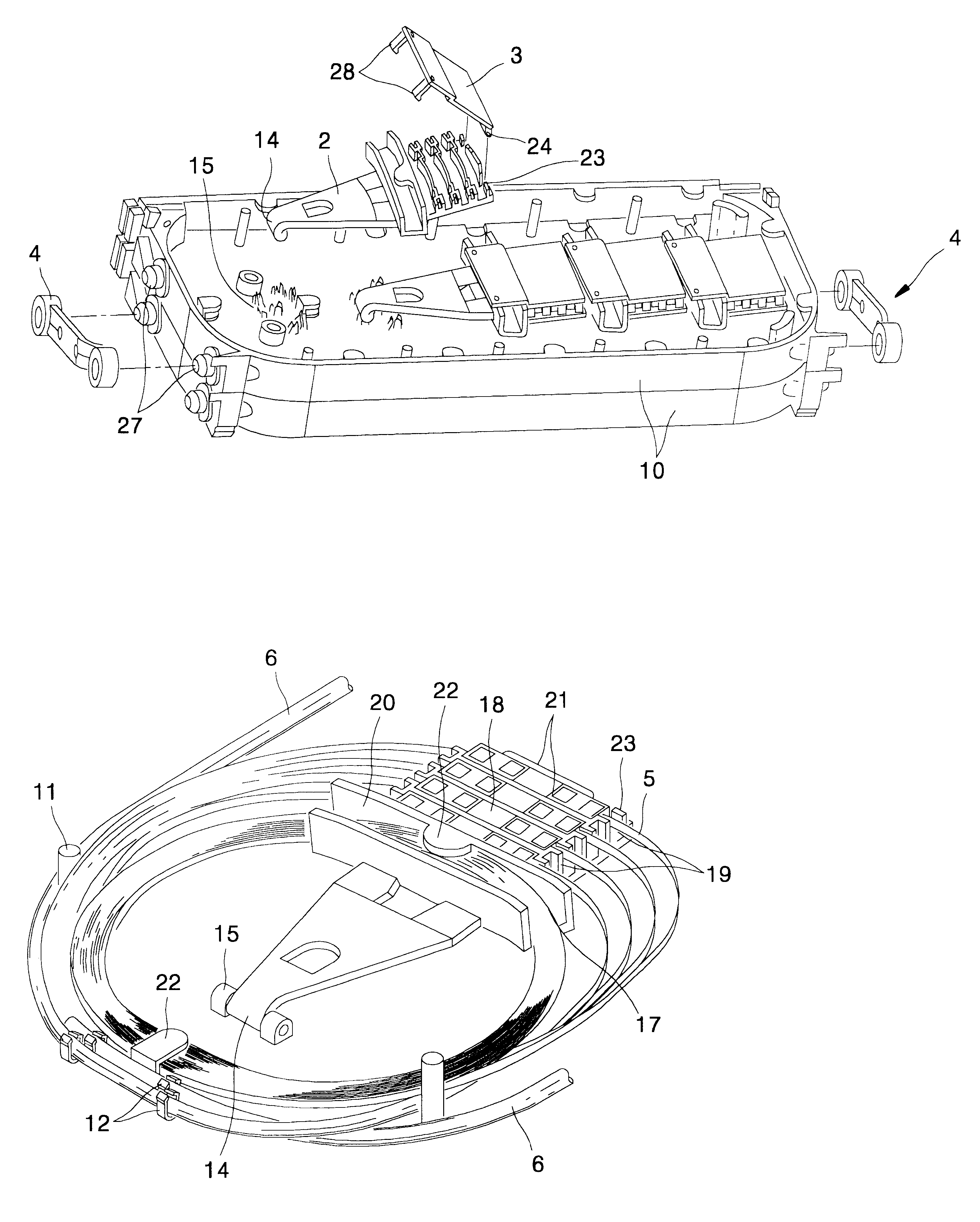
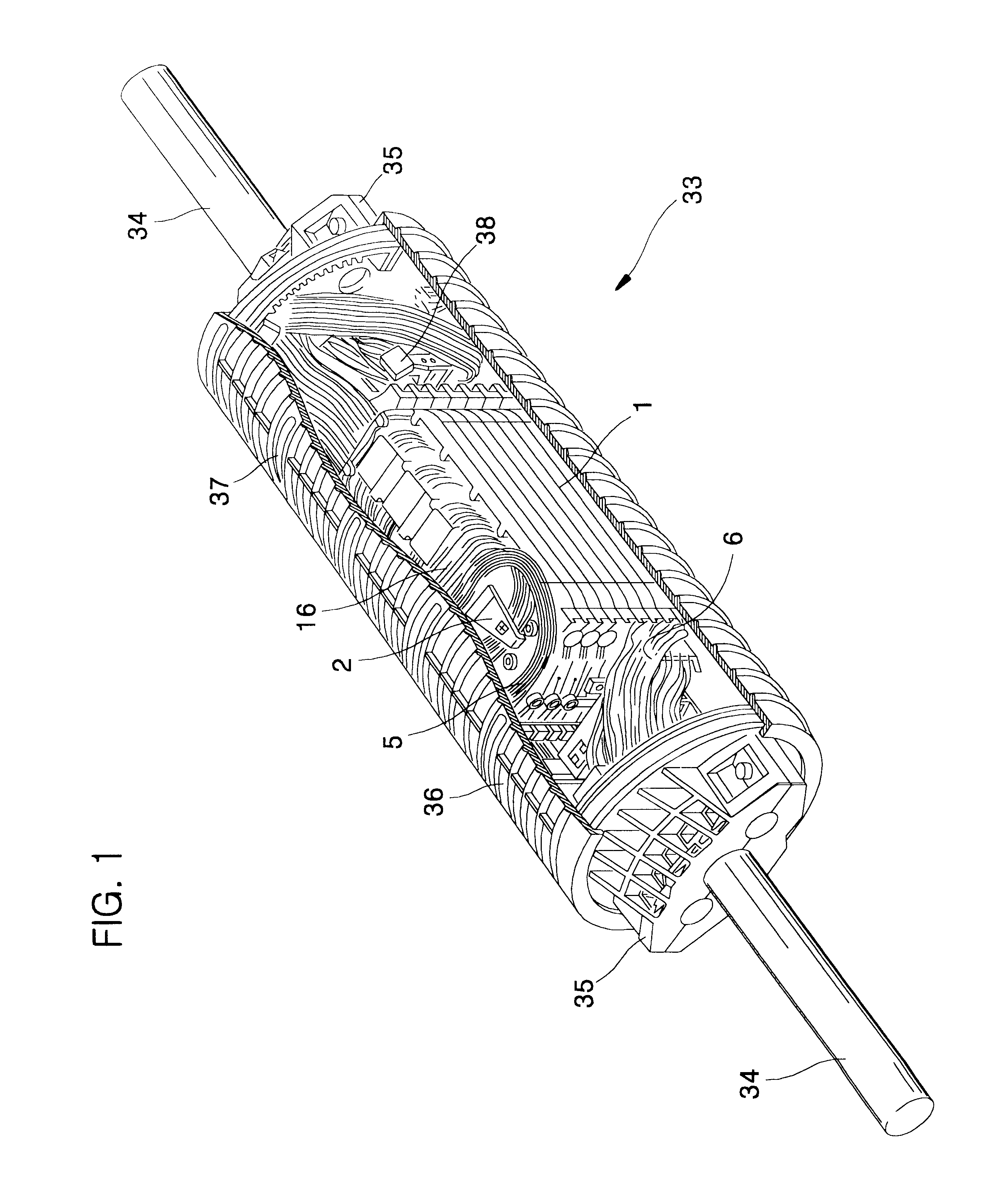
FIG. 1 is a perspective view showing an splice closure for optical ribbon fiber cable disposing trays for splicing optical ribbon fibers according to the present invention, with a part cut off.

As shown in FIG. 1, the optical ribbon fiber cables 34 are inserted into an splice closure 33 through each endcap 35 positioned in both ends of the splice closure 33. Further, the splice closure 33 has a plurality of trays for containing and protecting the optical ribbon fibers and splices therein. In this case, the tray main body 1 is positioned between the both endcaps 35, and then be fixed by a tension member holder 38 and a clamping bar firmly. The optical ribbon fiber cables 34 inserted in the splice closure 33 are stripped off their sheathes, and then their tension members are fixed in the tension member holder 38. In this case, the optical ribbon fiber 5 is inserted into...


PUM


Abstract

A tray for splicing optical ribbon fibers capable of storing and organizing ribbon fibers splices and excess length, improving accommodation density for the optical ribbon fiber by using new splice arrangement plate structure, including a tray main body having a plurality of supporting portions protruded on an outer side thereof; a plurality of inlet portions for providing inlet paths for protection tubes, each of the inlet portions being formed on the outer side; a pair of stacking bars having through holes rotatably supported by one of the supporting portions to stack another tray main body; a plurality of splice arrangement plates for organizing optical ribbon fibers, each of the splice arrangement plates being disposed on the main body; a number of organizing portions for fixing the optical ribbon fibers and arranging excess lengths of the optical ribbon fibers, each of said splice arrangement plates comprising a plurality of the organizing portions; and a plurality of covers for covering the splice arrangement plates, respectively, to prevent said splice and excess length positioned in organizing portions from being removed outward.

Description

1. Field of the InventionThe present invention relates to a tray for storing and organizing optical ribbon fiber splices and an excess length of the optical ribbon fiber easily. More particularly, it relates to a tray for splicing optical ribbon fibers capable of holding firmly splices used in the splicing between the optical ribbon fibers consisting of multifiber (i.e., 4 to 12 cores), improving accommodation density for the optical ribbon fiber splices and excess length by using the new splice arrangement plate structure.2. Description of Related ArtGenerally, as a result of spread of the high-speed broadband telecommunication, when optical lines are supplied to all homes, many optical fibers are required as well as the copper lines. Therefore, when it is intended to construct subscriber lines by means of the optical cable, an optical ribbon cable which is made of a plurality of optical fibers has been developed and used. The optical ribbon cable is manufactured by a plurality of ...

Claims


Application Information

Patent Timeline
Patent Type & Authority Patents(United States)
IPC IPC(8): G02B6/44G02B6/36
CPCG02B6/4455G02B6/4447G02B6/36
Inventor KIM, GEUN YOUNGAHN, JEONG GYUNKIM, CHANG HA
Owner KT CORP
Why Eureka
Try Eureka