Check patentability & draft patents in minutes with Patsnap Eureka AI!

Air dispensing and heating floor drying apparatus

a technology of air dispensing and heating floor, which is applied in the direction of drying machines, lighting and heating apparatus, drying machines, etc., can solve the problem that none of the prior art inventions allow for the drying of carp

Inactive Publication Date: 2001-03-20
TURNER IV WILLIAM
View PDF7 Cites 40 Cited by
  • Summary
  • Abstract
  • Description
  • Claims
  • Application Information

AI Technical Summary

Benefits of technology

It is another object of the present invention to provide an improved carpet and flooring drying device that can be used either as a conventional blower or a heated air blower.
It is a feature of the present invention to provide an improved air dispensing and heating floor drying apparatus that can be adapted for directional heating for such tasks as thawing frozen pipes.
Placed at floor level, the invention forces warm-to-hot air across the floor surface to cause drying. Designed for commercial use, the invention provides a steady flow of heated air that cuts the time needed for complete drying of the floor. A fan forces air over the heated coils at the nozzle of the invention. The coils warm the air increasing the drying ability of the forced air. Temperature is regulated to produce air within a range of warm-to-hot. A handle at the top of the invention allows it to be maneuvered to direct air around the room and to other areas. It can also serve as a carrier for the invention.
Advantages of the present invention are many that would make it beneficial to both consumers and manufacturer. The simple design blends in with existing product lines at the manufacturing level, and can be used in conjunction with existing tools and hardware products. Regulated coils heats forced-air to desired temperature to increase drying power, and the ability to select temperature level allows for best results. The insulated housing protects components as well as people and exterior surfaces from hot coil.

Problems solved by technology

However, none of the inventions of the prior art allow for the drying of carpet from underneath the carpet, from above the carpet in a rotational drying pattern, and also use of the device as a conventional portable blower.

Method used


Image

  • Air dispensing and heating floor drying apparatus
  • Air dispensing and heating floor drying apparatus
  • Air dispensing and heating floor drying apparatus

Examples


Embodiment Construction

of the Figures

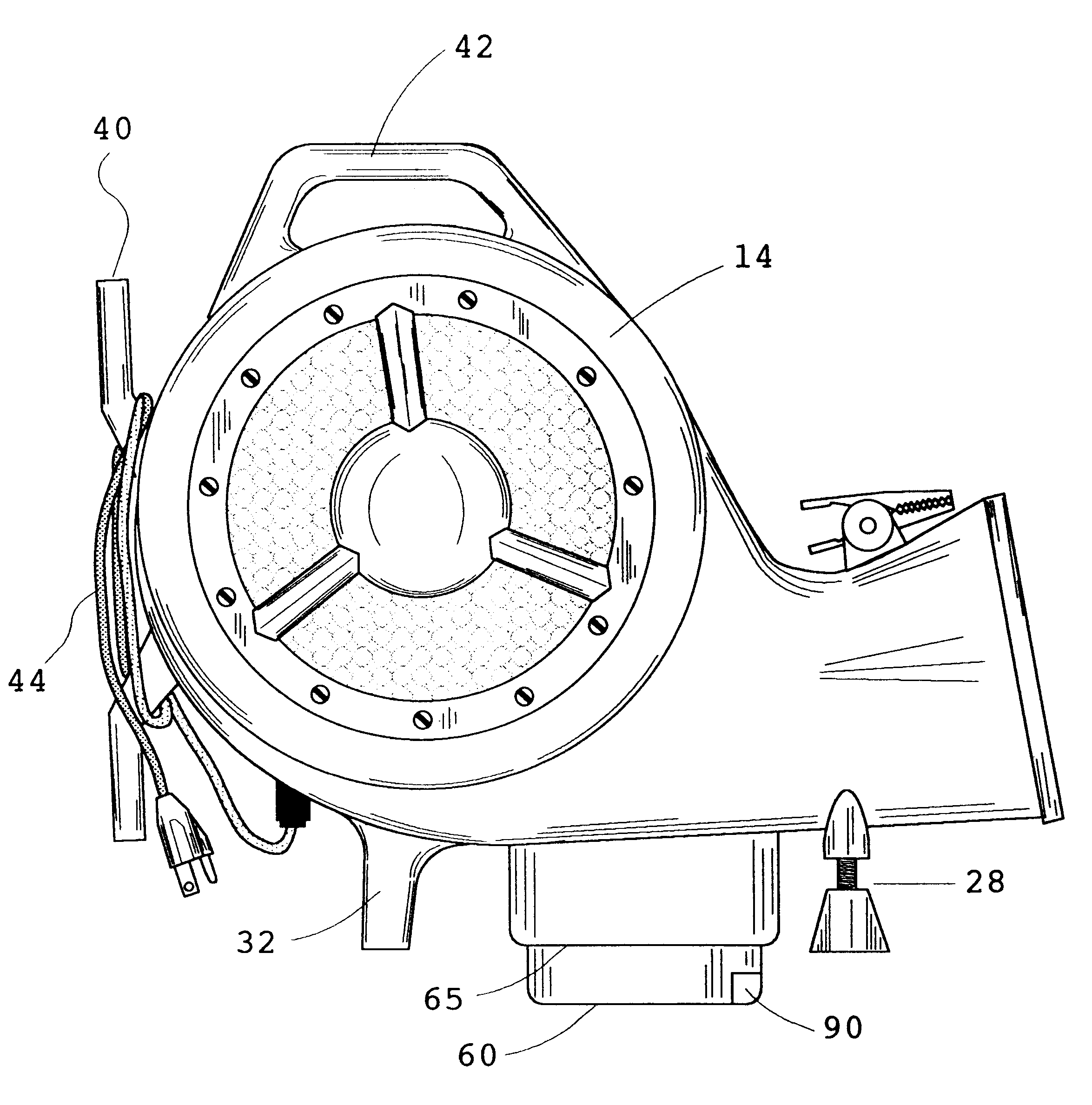
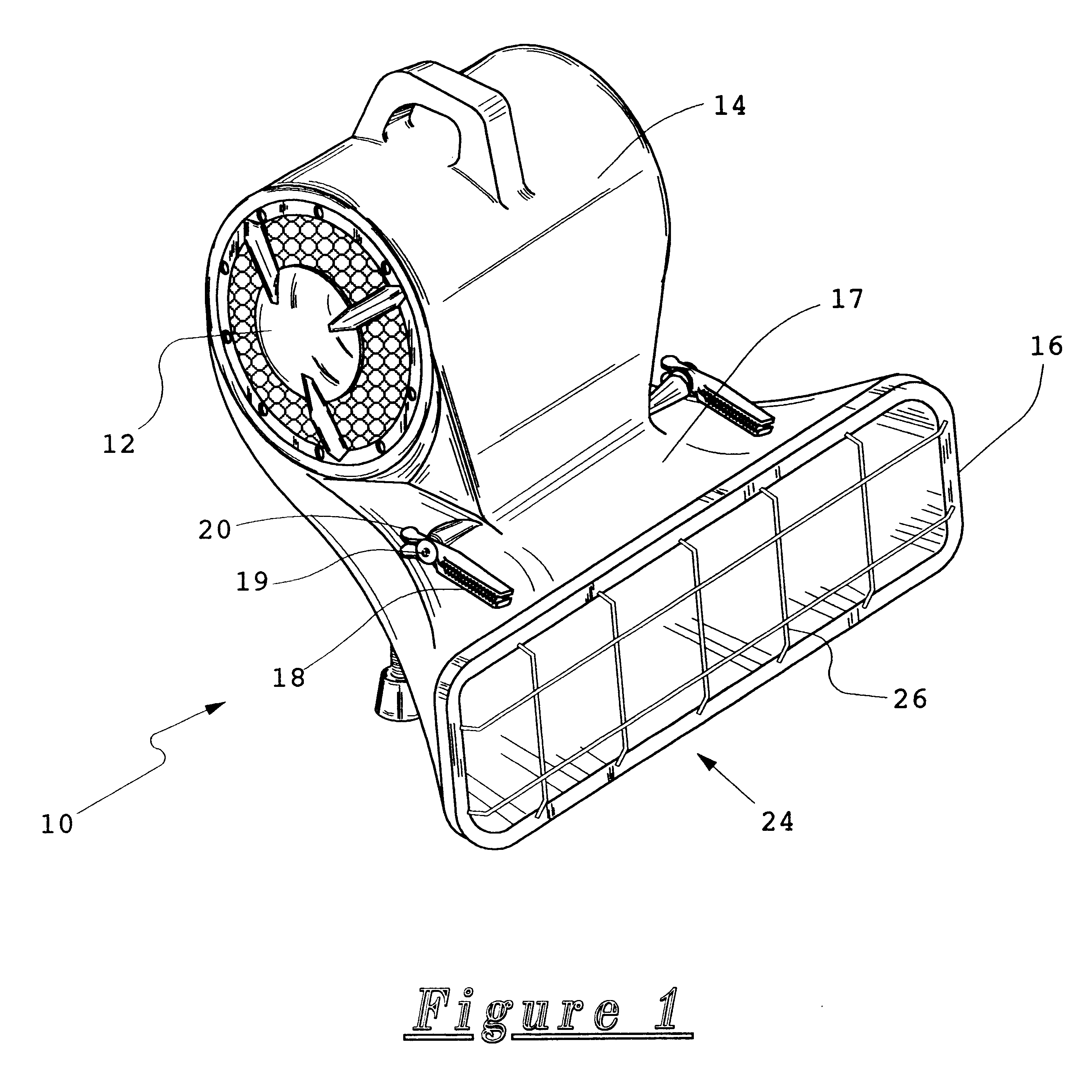
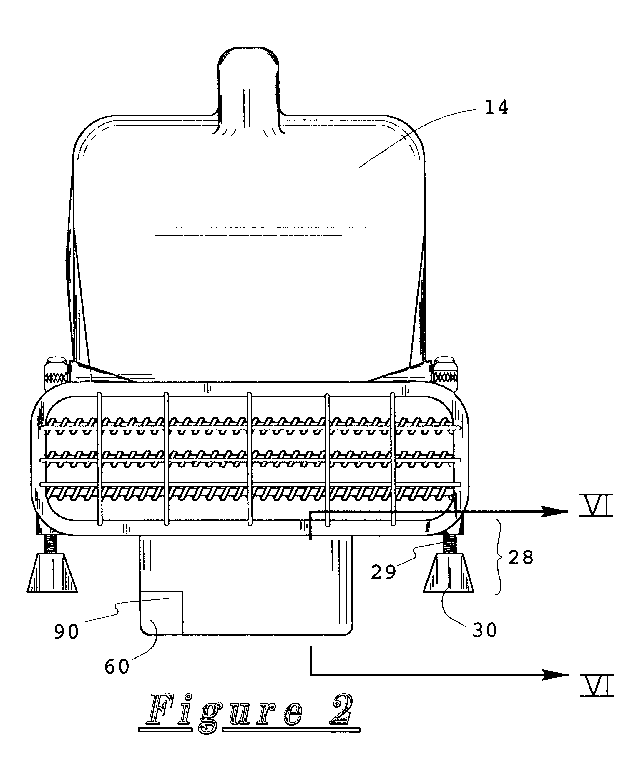
Referring now to FIG. 1, an air dispensing and heating floor drying apparatus 10 is disclosed according to the preferred embodiment of the present invention. A multi-speed, blower motor 12 is housed within a blower housing 14 of insulated, plastic material. The blower motor 14 is in fluid communication with a discharge nozzle 16. The blower motor 14 is envisioned as of an otherwise conventional squirrel cage type, and is capable of drawing ambient air and delivering it in a projected fashion through a discharge nozzle 16. The discharge nozzle 16 forms a flat upper surface 17 and further includes a slightly flared configuration for allowing an outward dispersement of airflow discharged from the nozzle 16. The flat upper surface 17 is opposed to a spring clip 18. The spring clip 18 has a spring means 19 for generating a downward clamping force upon a clamp arm 20. It is envisioned that the outer edge of a rug or carpet can be clamped between the clamp arm 20 and the uppe...


PUM


Abstract

An apparatus for drying damp carpet and flooring materials in either a heated or non-heated manner is disclosed. A blower is provided which incorporates coils located near or at the air flow entrance. A fan is included to produce the air. Designed for commercial carpet cleaning, the invention sits at floor level. The invention forces warm-to-hot air across the floor surface. A control is incorporated in the design to regulate the temperature of the forced air. A handle is designed with the housing of the blower on the top portion for carrying ease. The present invention rotates about a base to dry larger areas of flooring.

Description

1. Field of the InventionThe present invention relates generally to air blowers and, more particularly, to an air dispensing and heating floor drying apparatus.2. Description of the Related ArtIn the related art, many air blower and air heater devices have been improved and disclosed. However, none of the inventions of the prior art allow for the drying of carpet from underneath the carpet, from above the carpet in a rotational drying pattern, and also use of the device as a conventional portable blower.A search of the prior art did not disclose any patents that read directly on the claims of the instant invention; however, the following references were considered related:Of considerable relevance is U.S. Pat. No. 5,174,048, which discloses a carpet dryer similar in overall nature to the present invention. While a securing mechanism for maintaining the edge of a carpet on the upper surface of the air outlet portion of the device is incorporated into this invention in combination, ot...

Claims


Application Information

Patent Timeline
Patent Type & Authority Patents(United States)
IPC IPC(8): F26B21/00
CPCF26B21/001
Inventor TURNER, IV, WILLIAM
Owner TURNER IV WILLIAM
Features
  • R&D
  • Intellectual Property
  • Life Sciences
  • Materials
  • Tech Scout
  • Unparalleled Data Quality
  • Higher Quality Content
  • 60% Fewer Hallucinations
Learn More