Self opening line of pliers

Inactive Publication Date: 2001-03-20
DOLAN MICHAEL
View PDF14 Cites 58 Cited by
  • Summary
  • Abstract
  • Description
  • Claims
  • Application Information

AI Technical Summary

Benefits of technology

FIG. 8 is a perspective view of said invention, showing the self opening wire cutter, pliers in lock position. The spring is in a compressed position and the latch is also in the lock position. The handles are shown with a rubber like material jacket, to provide comfort to the hand and protect from possible electric contact.
FIG. 9 is an orthographic view of said invention. The wire cutter pliers are shown in the lock position, showing the spring compressed and the plier jaw closed. Also shown are the rubber like material ...

Problems solved by technology

The multipurpose tool of the present disclosure is composed of a material of good wear resistance, toughness and hardness and has a disadvantage in that all of the manual works, for example, stripping of an elec...

Method used


Image

  • Self opening line of pliers
  • Self opening line of pliers
  • Self opening line of pliers

Examples


Embodiment Construction

)

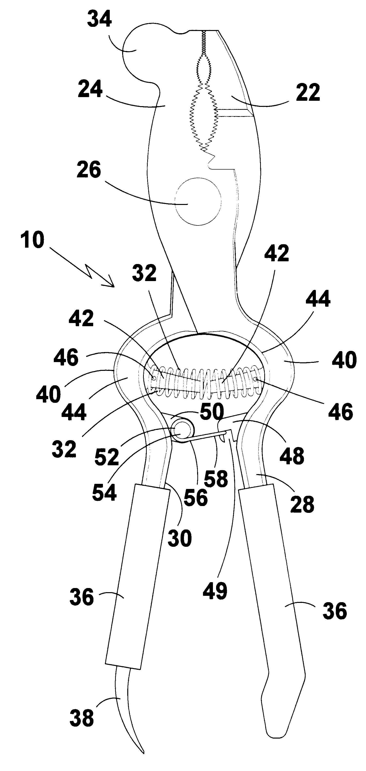
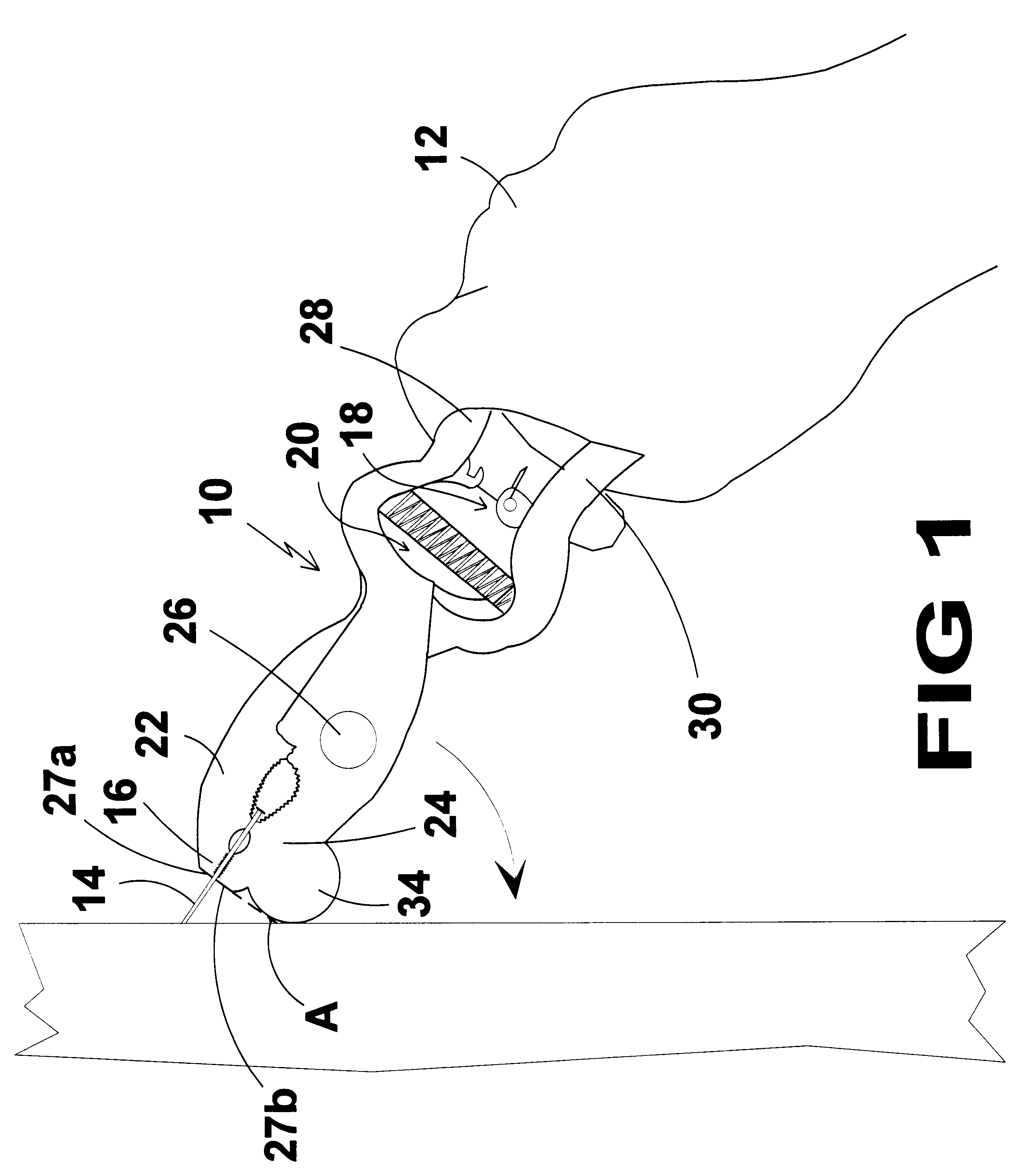
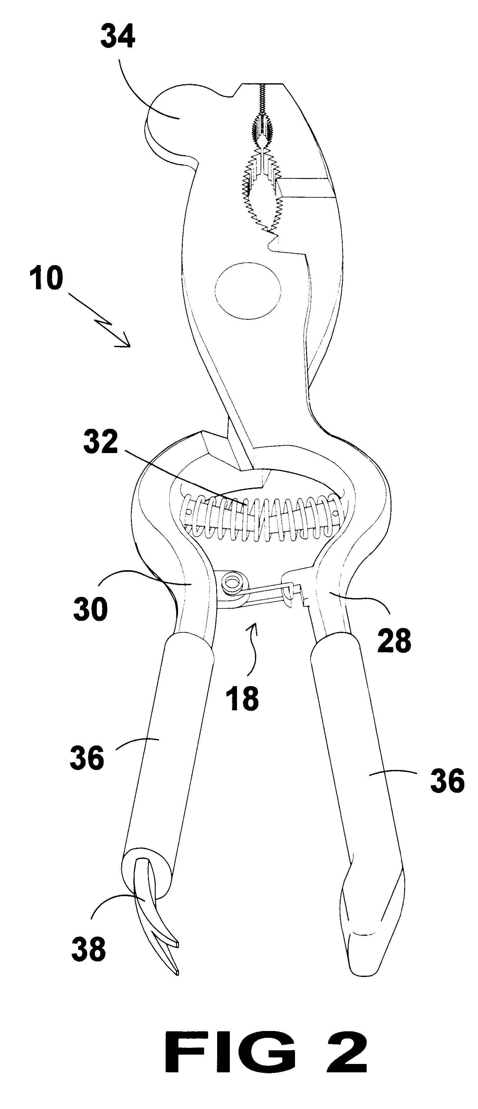
In order that the invention may be more fully understood, it will now be described, by way of example, with reference to the accompanying drawings in which FIGS. 1 through 14 illustrate the present invention being self-opening pliers.

Turning to FIG. 1, shown therein is an illustration of the present invention 10 depicting the self-opening pliers in use in the hand 12 of a user. The combination tool comprises a set of self-opening pliers. FIG. 1 also illustrates the multipurpose solid means for leverage piece 34 being an enlarged member on the back of a jaw 24, to remove any number of stuck, rusted, or unwanted nails or staples 14. Also shown are the grip like teeth 16, used as a conventional plier. The latch or lock system 18 is shown open. The spring system 20, squeezed together by illustrated hand 12 closing the jaw members 22, 24. When the user releases hand 12 pressure on the invention 10, the jaws 22, 24 are forced open by the spring system 20. Pivot 26 and handles 28, 30 are ...


PUM


Abstract

The present invention 10 discloses a spring system 20 and a latch system 18 for either maintaining a set of pliers in an open position or a closed position. The spring system 20 operates by having a spring 32 disposed on a pair of studs 42 located in the trough 44 of an outwardly curved portion 40 of the handles 28, 30 of the pliers. The latch system 18 comprises a pair of tongue-like members 48, 50 and a wire loop member 58 which hooks onto a notch 49 in one of the tongue-like members 50. The spring system 20 normally maintains the pliers in an open position when no load is applied to handles 28, 30.

Description

1. Field of the InventionThe present invention relates generally to pliers and more specifically to variously shaped hand tools having pivoting jaws which are designed to hold, bend, twist or cut, such as, pliers, linesman pliers, wire cutters, and needle nose pliers, hereinafter referred to as pliers. The pliers have specially designed handles having an outwardly projecting recessed curve below the pivot point having oppositely opposed studs at the trough of the recessed curve projecting inwardly whereupon is mounted a coiled spring, held on by nubs located on studs, being of such a compressed state as to cause the handle members, under a no load condition, to naturally pivot to a fully open position. Further situated at the apex of the curved recesses are oppositely opposed inwardly projecting tongue-like members. The first tongue-like member has a notch and the second tongue-like member has an aperture having a rivet passing therethrough having a wire member wrapped around each e...

Claims


Application Information

Patent Timeline
IPC IPC(8): B25B7/00B25B7/14B25B7/22B25B7/02B25C11/00
CPCB25B7/02B25B7/14B25B7/22B25C11/00
Inventor DOLAN, MICHAEL
Owner DOLAN MICHAEL
Why Eureka
Try Eureka