Animal waste disposal system

a waste disposal system and animal technology, applied in the field of automatic waste removal systems, can solve the problem of animal waste falling into the waste container

Inactive Publication Date: 2001-03-20
ATCRAVI ITTY
View PDF20 Cites 97 Cited by
  • Summary
  • Abstract
  • Description
  • Claims
  • Application Information

AI Technical Summary

Benefits of technology

It is therefore an object of the present invention to provide an automatic waste removal system for animal with a safe waste-removing mechanism. Another object is to provide a waste-removing mechanism which is capable of removing substantially smaller

Problems solved by technology

Further pivoting of the scoop causes anima

Method used


Image

  • Animal waste disposal system
  • Animal waste disposal system
  • Animal waste disposal system

Examples


second embodiment

Description of the Second Embodiment

Another method of pivoting a scoop to remove animal's waste from different sections of a bed of particulate litter involves the use of tracks or guide rails positioned on opposite sides of the litter tray to engage with levers or fingers connected to the axis of rotation of the scoop as the latter is moved laterally. FIGS. 7, 8, 9 and 10 show the second embodiment of the present invention which employs this type of mechanism to remove animal's waste from three contiguous sections of the bed of particulate litter.

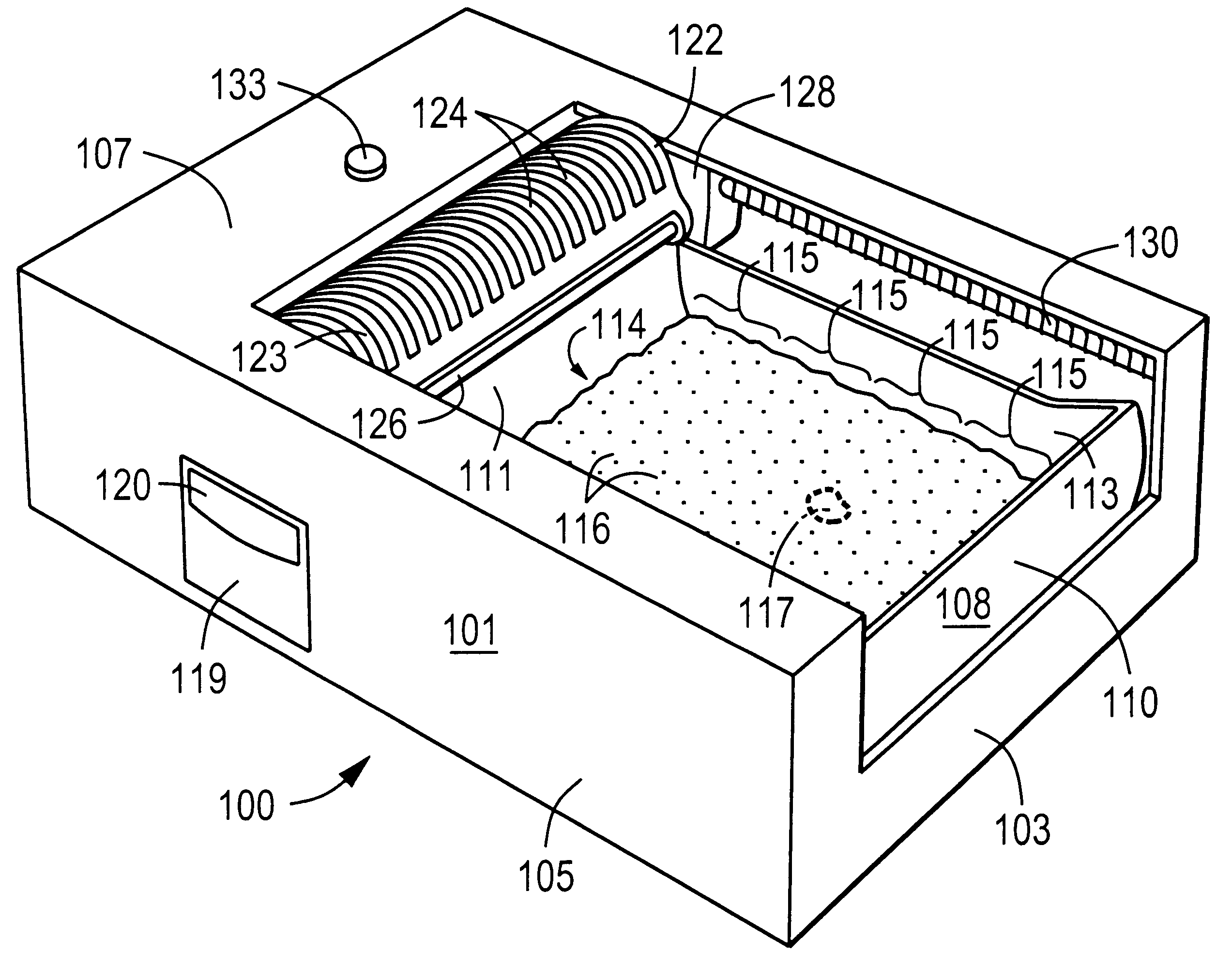
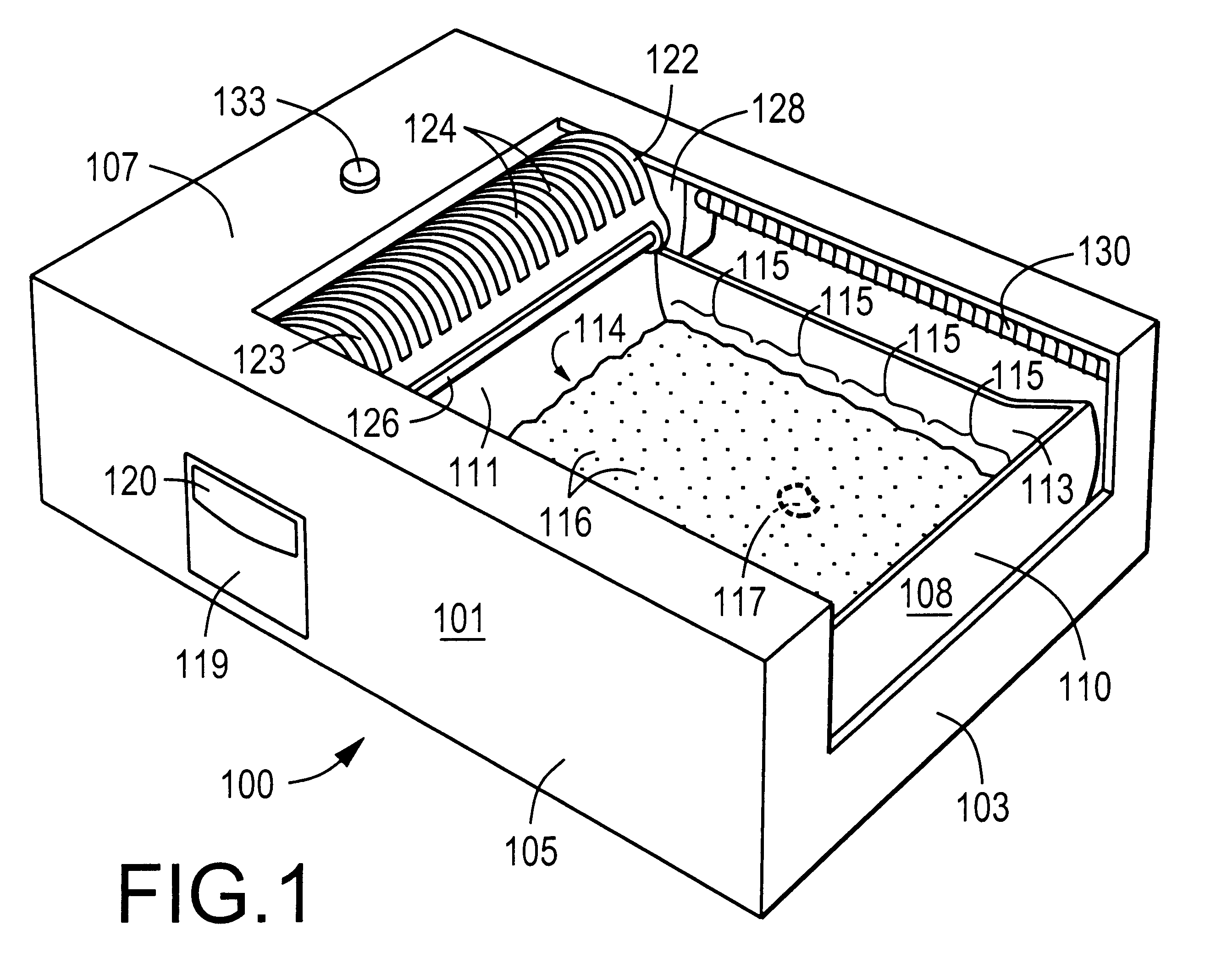
The animal waste disposal system 200 includes a housing 201 having a supporting base 202, a front wall 203, two outer side walls 204, 205, an outer rear wall 206, two inner side walls 207, 208, an inner rear wall 209 and a top panel 210.

A removable litter tray 211 is positioned on supporting base 202 between inner side walls 207 and 208. It comprises a bottom floor 212, a front curved end 213, a rear curved end 214, and two opposite side w...

first embodiment

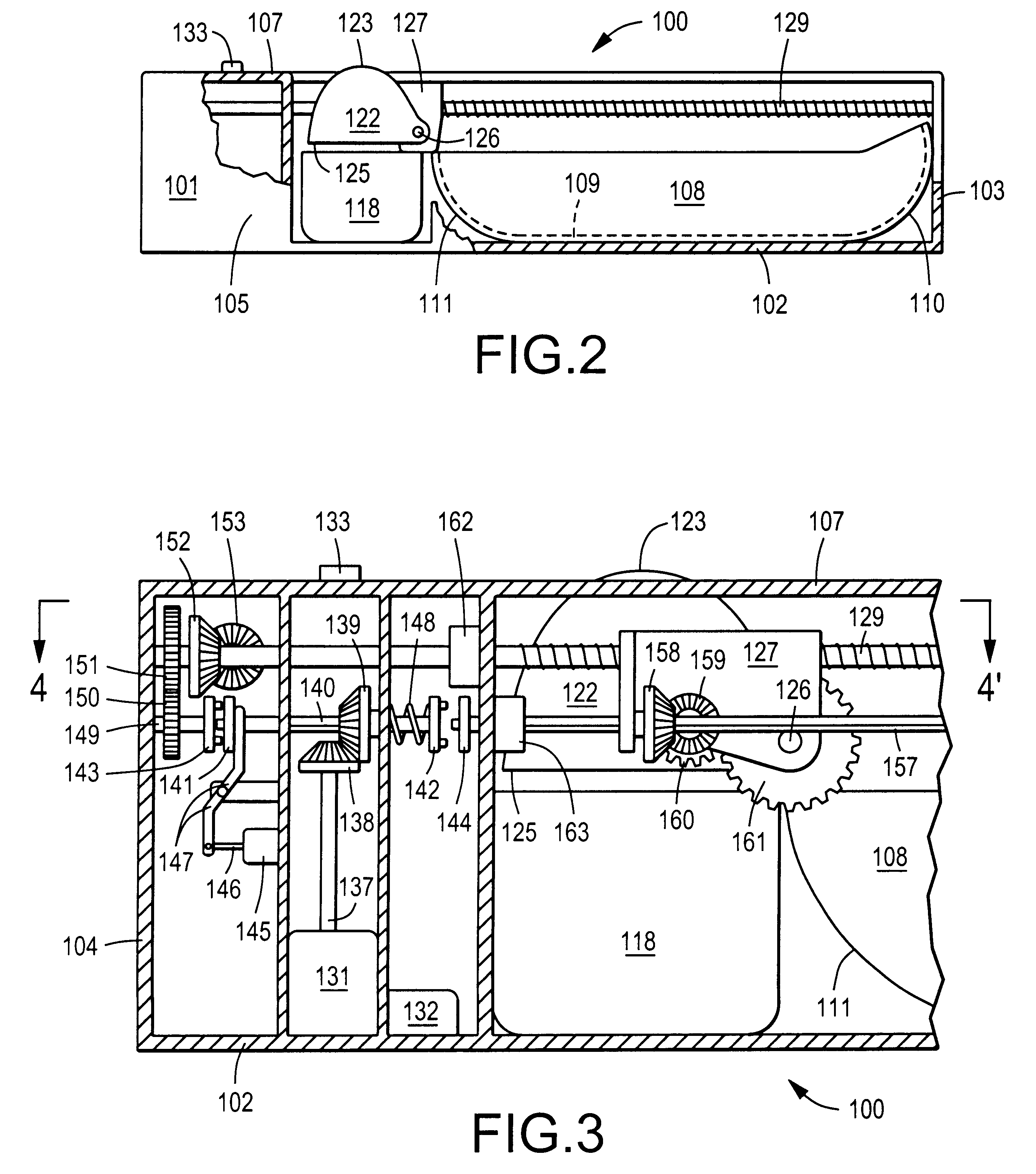
FIGS. 11A to 11F are sectional side views of the middle and rear sections of the animal waste disposal system 200 showing six different positions of the waste-removing mechanism during a process of removing animal's waste from the rear section of litter tray 211. The litter and animal's waste are not depicted in FIGS. 11A to 11F in order to avoid confusion but it can be seen that the waste-scooping process for this embodiment is similar to the process described for the

The waste-removing operation begins with scoop 222 in its storage position shown in FIG. 11A. The user presses push button 229 to cause controller 228 to energize electric motor 227. Electric motor 227 rotates shaft 232 which is connected to bevel gear 233 in the clockwise direction (with respect to FIG. 8). Bevel gear 233 in turn rotates bevel gear 234 which is connected to horizontal shaft 235. The motion is transferred to threaded rod 239 by means of bevel gear 236 and 238, and to threaded rod 241 by means of bevel ...

third embodiment

Description of the Third Embodiment

It is also obvious to those skilled in the art that either of the two waste-removing mechanisms described above may be made to operate in a fully automatic fashion with the use of one or more sensors for detecting the presence of an animal inside the housing. However, since most types of animal sensor are known to malfunction from time to time and since the waste-removing mechanism must be quite powerful to be able to move a substantial amount of animal's waste and particulate litter inside the litter tray, there is a possibility that the waste-removing mechanism will injure an animal during its fully automatic operation.

A solution to this problem is to provide a partition or cover which automatically extends across the bed of particulate litter before the waste-removing operation begins to make the waste-removing mechanism inaccessible to the animal. The third embodiment of the present invention contains this type of partition which is attached to...


PUM


Abstract

An animal waste disposal system including a housing with an area for holding a bed of particulate litter, a scoop with a plurality of perforations for separating animal's waste from the particulate litter, and a drive mechanism for moving the scoop to remove animal's waste from the bed of particulate litter. The waste-removing operation is carried out by collecting a mixture of animal's waste and particulate litter in the interior of the scoop and moving the scoop in a raised position over the area for holding the bed of particulate litter to allow the collected particulate litter to sift through the perforations in the scoop while retaining animal's waste for disposal into a waste container. The bed of particulate litter may be arbitrarily defined by a plurality of contiguous sections, each of which can be cleaned or processed separately and independently. Two types of retractable partitions are provided to make the waste-removing mechanism inaccessible to the animal during its automatic operation.

Description

The present invention pertains generally to an animal waste disposal system and method for removing animal's waste from a bed of particulate litter. More specifically, the present invention employs a mechanism for scooping animal's waste from a bed of particulate litter. Two types of retractable partitions are provided to prevent an animal from touching the waste-removing mechanism during its automatic operation.A variety of litter boxes or waste disposal systems exists with a mechanism for removing animal's waste from a bed of particulate litter. These systems may be classified into several categories based on their construction and functions. For example, one type of system includes a stationary litter tray with a rake, basket or scoop which moves along a predetermined path inside the litter tray to collect animal's waste from the bed of particulate litter. Another type of system uses a rotary litter container with a sifting screen positioned inside the container for separating an...

Claims


Application Information

Patent Timeline
IPC IPC(8): A01K1/01
CPCA01K1/0114
Inventor ATCRAVI, ITTY
Owner ATCRAVI ITTY
Why Eureka
Try Eureka