Securing device and linear guiding mechanism

a technology of guiding mechanism and guiding device, which is applied in the direction of bearings, shafts and bearings, bearings, etc., can solve the problems of heavy and bulky, and achieve the effect of reliable supporting strength

Active Publication Date: 2018-10-18
THK GMBH +1
View PDF9 Cites 0 Cited by
  • Summary
  • Abstract
  • Description
  • Claims
  • Application Information

AI Technical Summary

Benefits of technology

[0004]Linear guides providing reliable supporting strength while fulfilling

Problems solved by technology

Linear guides providing reliable supporting strength while fulfilling th

Method used


Image

  • Securing device and linear guiding mechanism
  • Securing device and linear guiding mechanism
  • Securing device and linear guiding mechanism

Examples


Embodiment Construction

[0044]The following detailed description is merely exemplary in nature and is not intended to limit the present disclosure or the application and uses of the present disclosure. Furthermore, there is no intention to be bound by any theory presented in the preceding background on the following detailed description.

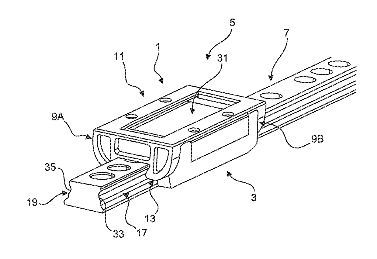
[0045]FIG. 1 shows a perspective schematic view of a linear guiding mechanism 5 with a movable unit 3, a guiding rail 7 and a securing device 1 according to an exemplary embodiment of the present disclosure.

[0046]The movable unit 3 is movably engaged with guiding grooves 17, 19 provided on opposite sides of the guiding rail 7 by means of bearings (not shown in FIG. 1). In this way, the movable unit 3 is movable on the guiding rail 7 along the extension direction of the guiding rail 7.

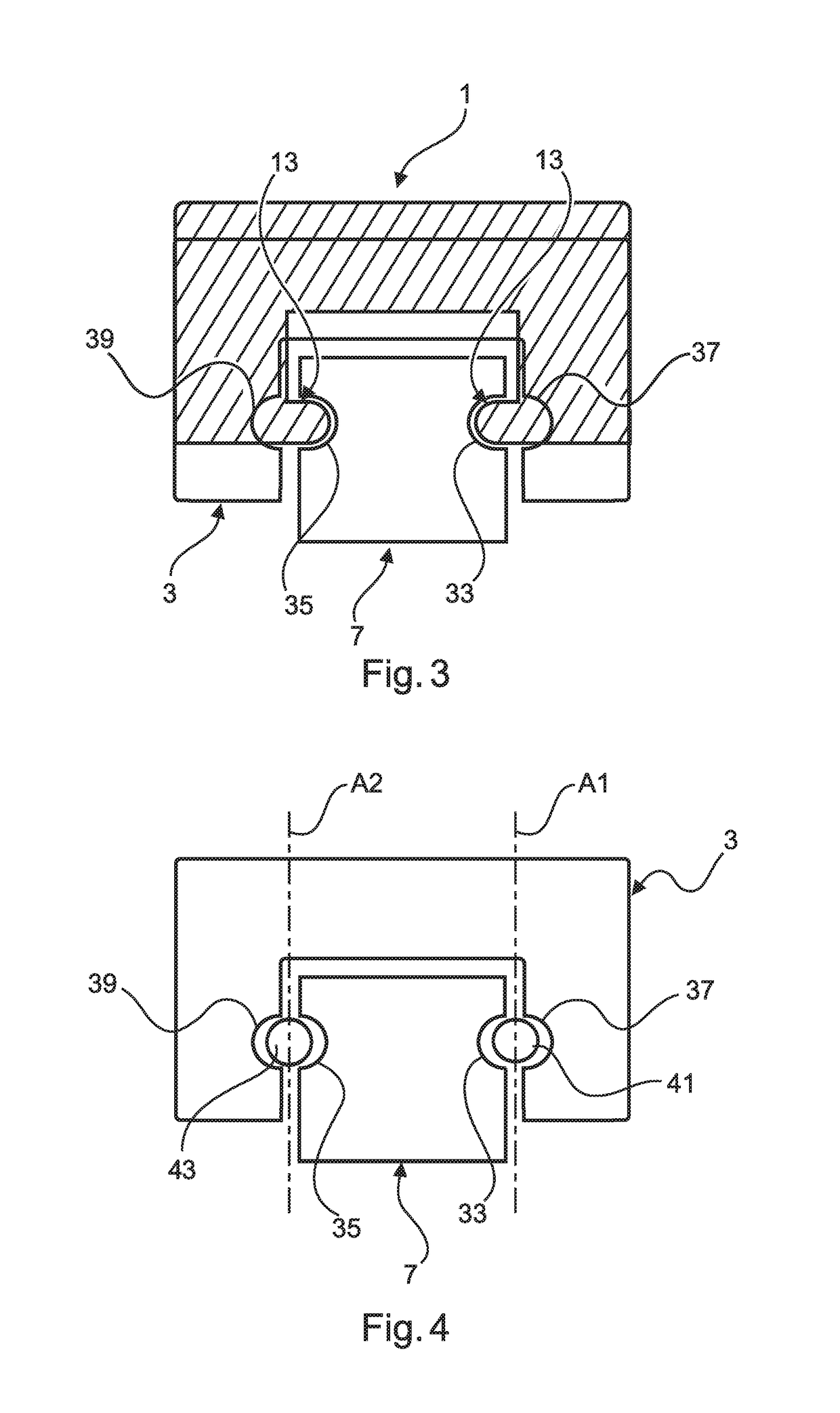
[0047]As is shown in FIGS. 1, 3 and 4, the guiding rail 7 comprises ball races 33, 35 in the respective guiding grooves 17, 19 which provide a support for balls 41, 43 of a linear ball bearing....


PUM


Abstract

Disclosed is a securing device for providing a movable unit of a linear guiding mechanism with additional safety in that the securing device prevents the movable unit from coming off a guiding rail in case of a bearing malfunction. The securing device comprises at least one securing portion and a coupling portion for coupling the at least one securing portion to the movable unit. The securing portion is engageable with the guiding rail in case of a failure of the movable unit.

Description

CROSS-REFERENCE TO PRIORITY APPLICATIONS[0001]This application is a continuation of international patent application number PCT / EP2016 / 082299, having an international filing date of Dec. 22, 2016, which claims priority to German patent application number 102015122675.8, having a filing date of Dec. 23, 2015. The content of the referenced applications is incorporated by reference herein.TECHNICAL FIELD[0002]The technical field relates to a securing device configured to be coupled to a movable unit of a linear guiding mechanism and configured to secure the movable unit to a guiding rail of the linear guiding mechanism. Furthermore, the technical field relates to a linear guiding mechanism comprising a securing device.BACKGROUND[0003]Linear guiding mechanisms comprising movable units can be used for movably supporting elements in an aircraft. Such linear guiding mechanisms may comprise a guiding rail and a movable unit movably mounted on the guiding rail. The movable unit can withstand...

Claims


Application Information

Patent Timeline
IPC IPC(8): F16C29/06
CPCF16C29/0609F16C29/0638F16C29/064F16C29/10F16C29/0607
Inventor GROSS, CLAUS-PETERSCHOMACKER, LARSROLLFINK, PATRICKSIEHNDEL, DIANAHOSAKA, EIJIBERGER, TORSTEN
Owner THK GMBH
Why Eureka
Try Eureka