Gas-shielded AC arc welding method and machine making use of consumable electrode

a consumable electrode and arc welding technology, applied in the direction of arc welding apparatus, welding apparatus, manufacturing tools, etc., can solve the problems of large spatters splashing, unstable arc, shallow penetration,

Inactive Publication Date: 2001-03-27
HITACHI SEIKO LTD +1
View PDF2 Cites 40 Cited by
  • Summary
  • Abstract
  • Description
  • Claims
  • Application Information

AI Technical Summary

Problems solved by technology

Direct current (DC) arc welding is seldom performed by straight polarity alone (hereinafter called "EN polarity"), because EN polarity tends to form a large droplet at a wire tip, an arc is unstable, large spatters are splashed, and penetration is shallow.
Accordingly, the stability of an arc is impaired if the length of the arc is shortened and short circuiting is developed.
Further, when the welding current level becomes higher, that is, the wire feeding rate becomes faster, the period of an EN polarity current becomes shorter, thereby making it impossible to utilize characteristic features of welding in an EN polarity period, such as shallow penetration and high wire melting rate.

Method used


Image

  • Gas-shielded AC arc welding method and machine making use of consumable electrode
  • Gas-shielded AC arc welding method and machine making use of consumable electrode
  • Gas-shielded AC arc welding method and machine making use of consumable electrode

Examples


first embodiment

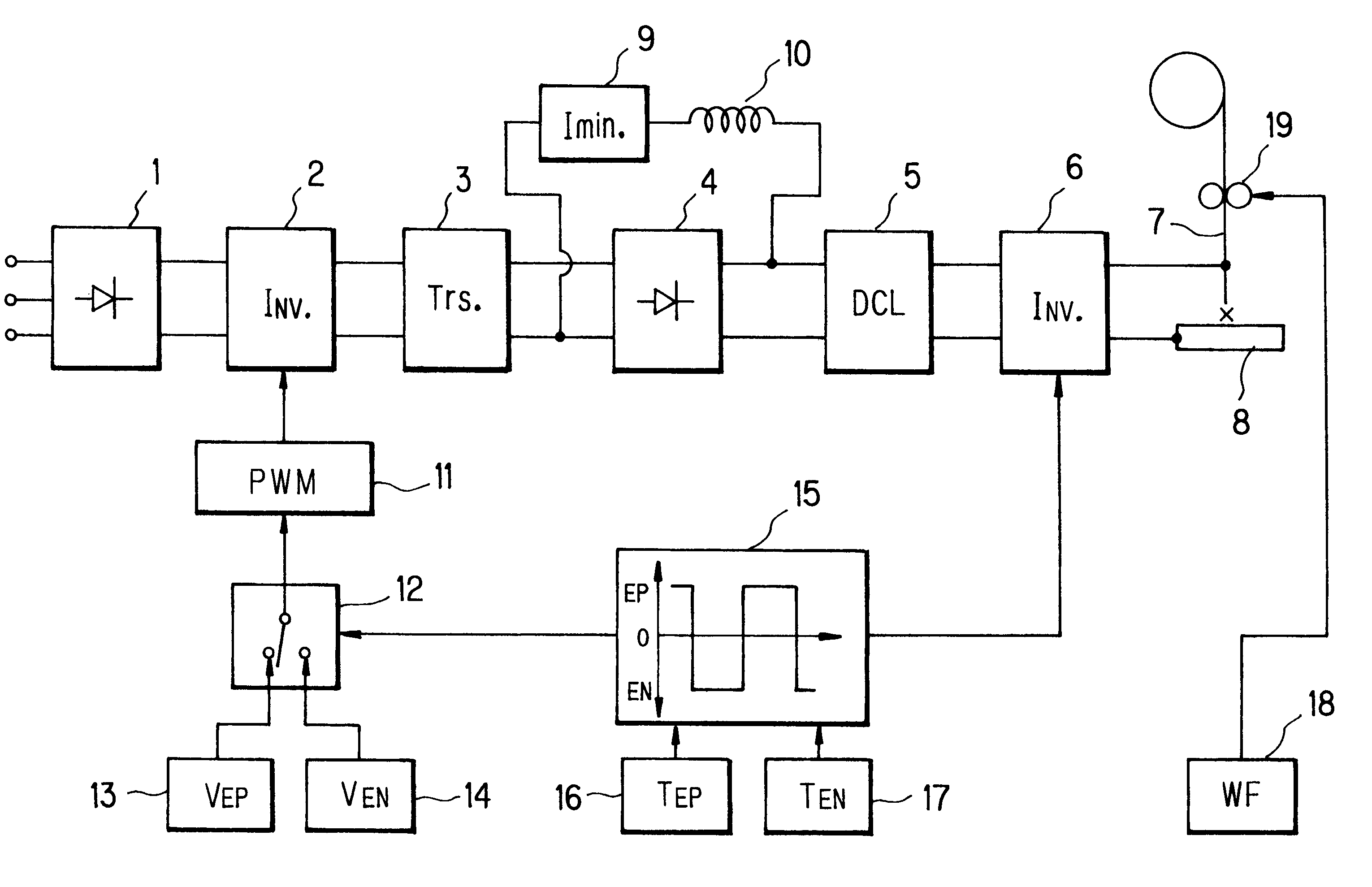
The welding machine according to the present invention will first be described with reference to FIG. 3. Designated at numeral 1 is a primary rectifier, which is connected at an input side thereof to a commercial AC power source and at an output side thereof to an input side of a primary inverter 2. Numeral 3 indicates a welding transformer, which is connected at an input side thereof to an output side of the primary inverter 2 and at an output side thereof to an input side of a secondary rectifier 4. The secondary rectifier 4 is connected at an output side thereof to an input side of a secondary inverter 6 via a DC reactor 5. The secondary inverter 6 is connected at an output side thereof to a wire 7 and a base metal 8. Designated at numeral 9 is a minimum current compensator, which is a power supply of substantially constant current characteristics. The minimum current compensator 9 is connected at an terminal thereof to the input side of the secondary rectifier 4 and at an opposi...

second embodiment

The welding machine according to the present invention will next be described with reference to FIG. 4, in which elements of construction which are identical to the corresponding elements in FIG. 3 or have the same functions as the corresponding elements in FIG. 3 are identified by like reference numerals. A description of such elements is hence omitted herein. In FIG. 4, numeral 22 indicates a setting device for an AC frequency f.sub.AC (=1 / (T.sub.EP +T.sub.EN), and the setting device 22 is connected to a computing device 16a for a period T.sub.EP and also to a computing device 17a for a period T.sub.EN. Designated at numeral 23 is a setting device for an EP period time percentage .delta.(=100T.sub.EP / (T.sub.EP +T.sub.EN), and the setting device 23 is connected to the computing device 16a and also to the computing device 17a. Numeral 30 indicates a setting device for an average welding voltage V.sub.av, which is connected to the setting device 13, a setting device 31 and the wire ...


PUM

PropertyMeasurementUnit
voltageaaaaaaaaaa
AC frequencyaaaaaaaaaa

Abstract

An EP output voltage to be outputted during a period of EP polarity is set so that a welding current becomes equal to or lower than a critical current level, and an EN output voltage to be outputted during a period of EN polarity is set at a level lower than the EP output voltage. This makes it possible to substantially equalize a wire melting rate in the period of EN polarity and that in the period of EP polarity with each other. Even at such a short arc length as causing frequent short circuiting, gas-shielded AC arc welding making use of a consumable wire can be still performed stably so that high wire melting rate, shallow penetration, convex weld reinforcement and the like, which are characteristic features of AC welding, can each be set selectively at a desired level or in a desired shape depending on the application.

Description

a) Field of the InventionThis invention relates to a gas-shielded AC arc welding method and machine, which perform welding by supplying a substantially constant AC voltage between the consumable electrode, which is being fed at a substantially constant rate, and a workpiece.b) Description of the Related ArtDirect current (DC) arc welding is seldom performed by straight polarity alone (hereinafter called "EN polarity"), because EN polarity tends to form a large droplet at a wire tip, an arc is unstable, large spatters are splashed, and penetration is shallow. On the other hand, reverse polarity (hereinafter called "EP polarity") features a small droplet, a stable arc and deep penetration. EP polarity has found widespread utility, since good welding results are available not only in large current welding in which an arc length is great but also in so-called short-circuiting transfer welding in which welding is performed by reducing an arc length and frequently repeating short circuiti...

Claims


Application Information

Patent Timeline
Patent Type & Authority Patents(United States)
IPC IPC(8): B23K9/06B23K9/173B23K9/073B23K9/095H02M9/00
CPCB23K9/06B23K9/073B23K9/0731B23K9/173
Inventor MITA, TSUNEOSHINADA, TSUNEOICHIKAWA, KAZUSHIGESAKAMOTO, YOSHITAKANOMURA, KOJINISHIKAWA, SEIGO
Owner HITACHI SEIKO LTD
Why Eureka
Try Eureka