Electric rotating machine

a rotating machine and electric technology, applied in the direction of windings, cooling/ventilation arrangement, magnetic circuit shape/form/construction, etc., can solve the problems of limiting the height of the coil end, and the inability to wind the coil in alignmen

Inactive Publication Date: 2001-04-03
HITACHI LTD
View PDF14 Cites 100 Cited by
  • Summary
  • Abstract
  • Description
  • Claims
  • Application Information

AI Technical Summary

Problems solved by technology

With this method, however since the coils are wound with being twisted from the inner periphery side of the core, it is impossible to wind the coils in alignment, and there occurs many portions where the wires intersect or cross each other.
As a result of this, there is a limit for reducing the height of the coil ends.
However, there are still limits in the high density of the windings, and as well as in the height of the coil end.
Sho 56-110464 (1981) mentioned above, since the motor is constructed such that the axial length of the rotor is shorter than that of the stator, it is impossible for the rotor to effectively utilize the magnetic flux generated by the stator.
Therefore it has a drawback that the torque efficiency thereof is decreased when it is small-sized.
Also, since the wire becomes thick in the diameter when the output of the motor comes to be large, ineffective or useless apertures are formed between the coils.
This means that the spaces inferior in heat radiation are increased, in spite of the increase of heat generation due to the increase of the output.
However, when forming the resin molding together with the coils, there can be a problem in which an insulator film layer of the coil is broken, thereby resulting in a short circuiting between the wires or lines thereof.
In this instance, the aperture defined between the neighboring coil ends also come to be large, thereby forming the useless aperture between the coils.

Method used


Image

  • Electric rotating machine
  • Electric rotating machine
  • Electric rotating machine

Examples


Embodiment Construction

)

Hereinafter, electric rotating machines according to embodiments of the present invention will be fully explained by referring to the attached drawings.

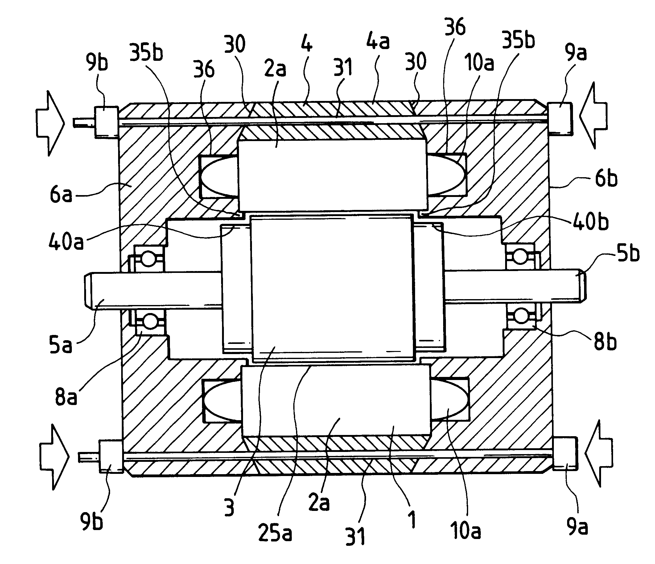
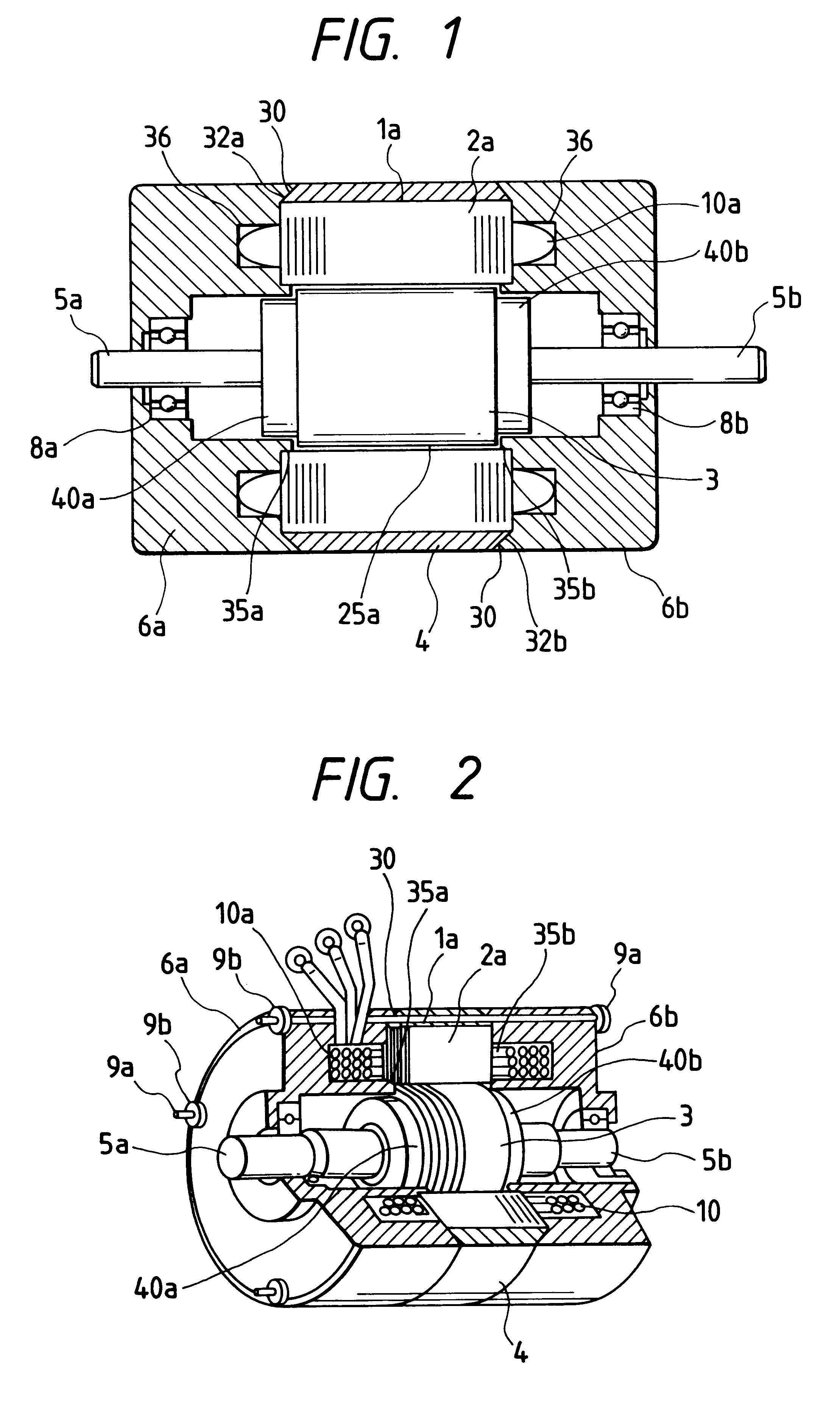
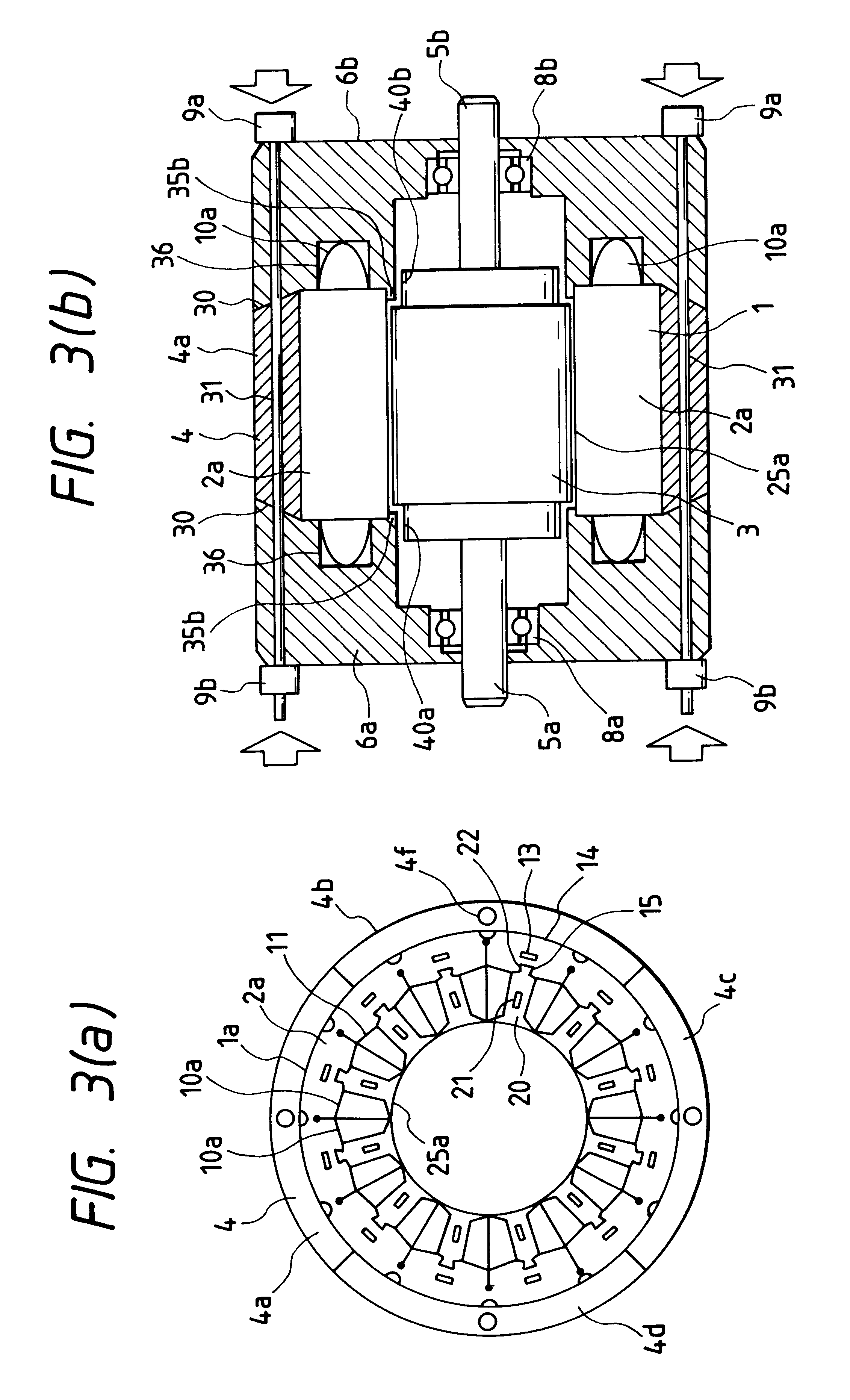
In FIG. 1, there is shown the basic construction of an electric rotating machine according to one embodiment of the present invention. Namely, the electric rotating machine, such as an induction motor, a synchronous motor, etc., according to the present invention, is constructed with a stator 1a and a rotor 3, wherein the stator 1a comprises a core 2a, being formed by compiling or laminating silicon steel plates, for example, and coils 10a which are inserted into slots 11 (shown in FIG. 3(a)) of the said core 2a with high space factor, thereby positioning or inserting the coils 10a into the slots with high space factor, which are provided in a large number thereof in the stator core 2a, as shown in the FIG. 3(a) . Also, the rotor 3 has such the structure that axes 5a and 5b are combined or connected to a portion forming the body of ...


PUM


Abstract

For achieving small-sizing and high efficiency by improving heat radiation of coils, and further for simple-construction to be easily disassembled, thereby being environment-friendly from a view point of recycling, an electric rotating machine comprising: a stator 1a being constructed by inserting coils 10a into slots 11 of a stator core 2a; an outer frame 4 being divided into a plurality thereof, so as to cover periphery of the stator core of said stator; a pair of bearing holder portions 6a and 6b, each having a fitting portion 35a or 35b to be fitted into an inner diameter reference surface 25a at both end portions of said stator and being provided with a bearing 8a or 8b at an axial center portion thereof, and being attached at both sides of said stator core so as to cover coil end portions dropping out at both sides of said stator; a squeezing mechanism (30, 32a, 32b, 6a, 6b) fixing the outer frame at an outer periphery of the stator core, by a wedge function between each of the bearing holder portions and the outer frame due to a squeezing function of attaching the each of said pair of bearing holder portions at both sides of said stator core; and a rotor 3 being formed with an escaping portion for escaping from an outer diameter of a portion opposing to a fitting portion of each of said bearing holder portion, rotatably positioned within said stator core.

Description

1. Field of the InventionThe present invention relates to electric rotating machines, each comprising at least a stator and a rotor therein, such as an induction motor, a synchronous motor, a magnet motor, etc.2. Description of Prior ArtAs conventional arts in relation to the above electric rotating machines are already known, for example, Japanese Patent Laying-Open No. Sho 56-110464 (1981), Japanese Patent Laying-Open No. Hei 3-190543 (1991), and Japanese Patent Laying-Open No. Hei 4-87537 (1992).In the Japanese Patent Laying-Open No. Sho56-110464 (1981), there is described a motor, wherein a bracket (i.e., a portion for holding the bearing) having a bearing for holding an axis of the rotor therein is held on an inner diameter portion (i.e., on an inner diameter reference surface) of the stator, thereby the axes of the above-mentioned stator and the above-mentioned rotor are combined coaxially.Also, in the Japanese Patent Laying-Open No. Hei 3-190543 (1991), there is described a f...

Claims


Application Information

Patent Timeline
Patent Type & Authority Patents(United States)
IPC IPC(8): H02K5/04H02K5/18H02K5/20H02K5/15H02K1/18
CPCH02K1/185H02K5/04H02K5/15H02K5/18H02K5/20H02K2201/09H02K5/203
Inventor ENOMOTO, YUJITANEDA, YUKINORIYAMAMOTO, NORIAKISHIBUKAWA, SUETAROSENOH, MASAHARUTAJIMA, FUMIO
Owner HITACHI LTD
Why Eureka
Try Eureka